Build Log: Ghostbusters Leg Hose Connector
Walkthrough how I designed and fabricated a rubber leg hose connector for my Ghostbusters uniform.
There’s a part of the Ghostbusters uniform that many people hate. You include it for accuracy, but it’s floppy, catches on things, and is just the last thing you want to have to worry about when you’re already paranoid about the wand’s wire loom catching on something or turning and taking something or someone out with your proton pack. I’m talking about the leg hose.
To prepare for SiliCon 2021, I wanted to remake my leg hose attachments to meet several criteria:
Make the connector out of rubber, like the screen-used pieces
Make the leg hose secure but detachable if it catches on something
Make the leg attachment something I could easily remove if I needed to wash the uniform or just didn’t want to wear it
The leg hose connector is a rubber piece attached to the left leg of the uniform. The leg hose fits inside and is held in place by friction and, optionally, a 4mm wide zip tie. The other end of the leg hose is often attached to the pistol belt or just looped under it. The connector itself is sewn onto the leg of the uniform.
There are many designs for the connector and alternatives for how it attaches to the uniform. Likewise, many people have come up with ways for the leg hose to attach to the back of the uniform or belt. The design I came up with involved 3D printed pieces with threads and magnets embedded inside a rubber mold. Since then, I’ve come across similar ideas that used machined parts and other alternatives. For such a small piece of a costume, it’s really cool to see how people have approached this part in slightly different ways based on their personal skill sets and preferences.
Dimensions and Planning
To get started, I headed to the Replica Prop Forums (RPF) to see if there were any threads with good reference images. This being a Ghostbusters prop, there were many to choose from. I felt very lucky when I discovered RPF user Kormier’s drawing of the leg hose with all of the dimensions. I don’t know if their dimensions are 100% accurate, but Kormier showed their work, and - once modeled and printed - I thought the connector looked very much correct.
Speaking of different approaches to this, Kormier turned their connector out of wood on a lathe! How cool is that?
I took Kormier’s dimensions and modeled the connector in Fusion 360. Once I was happy with the model, I printed it in ASA and prepared it for a mold - i.e., did a lot of sanding.
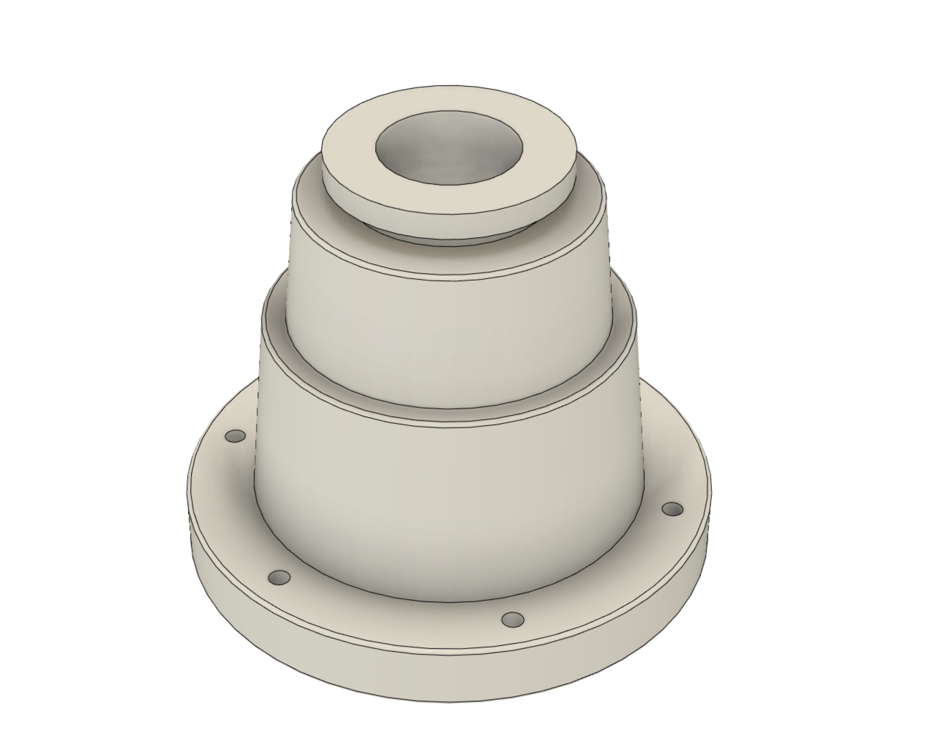
Model of the Leg Hose Connector in Fusion 360
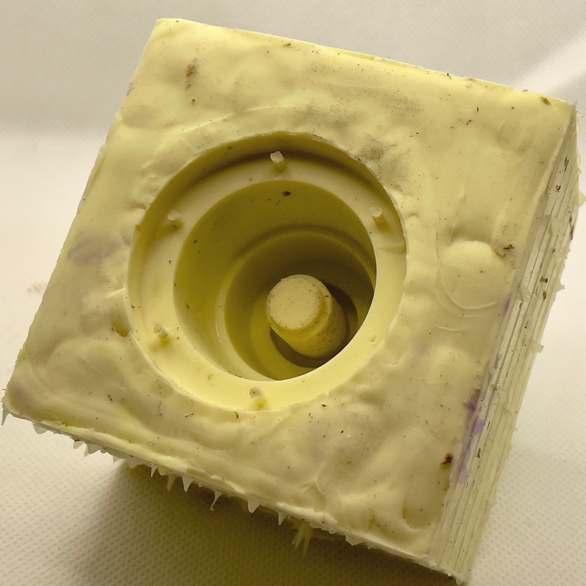
The connector had a flat bottom with no details, so I could make a very simple one-part mold. The one consideration I had to make was what to do about the thread holes. I didn’t want to be part of the mold because the silicone would be far too thin and floppy, but I also didn’t want to have to figure out where to make the holes every time I made a copy. The solution was easy: stick clay in the holes from the bottom so there would be partial holes on the top showing where to drill or insert a needle and thread.
Next, I cast a copy out of Smooth-On Econ 60 rubber. Econ 60 is a translucent amber color so I had to dye it to get the proper color. This turned out to be tougher than it seemed, but that challenge came later. The casting looked pretty good, so I knew the mold would work and the design was solid. Now it was time to figure out how to attach it to my uniform.
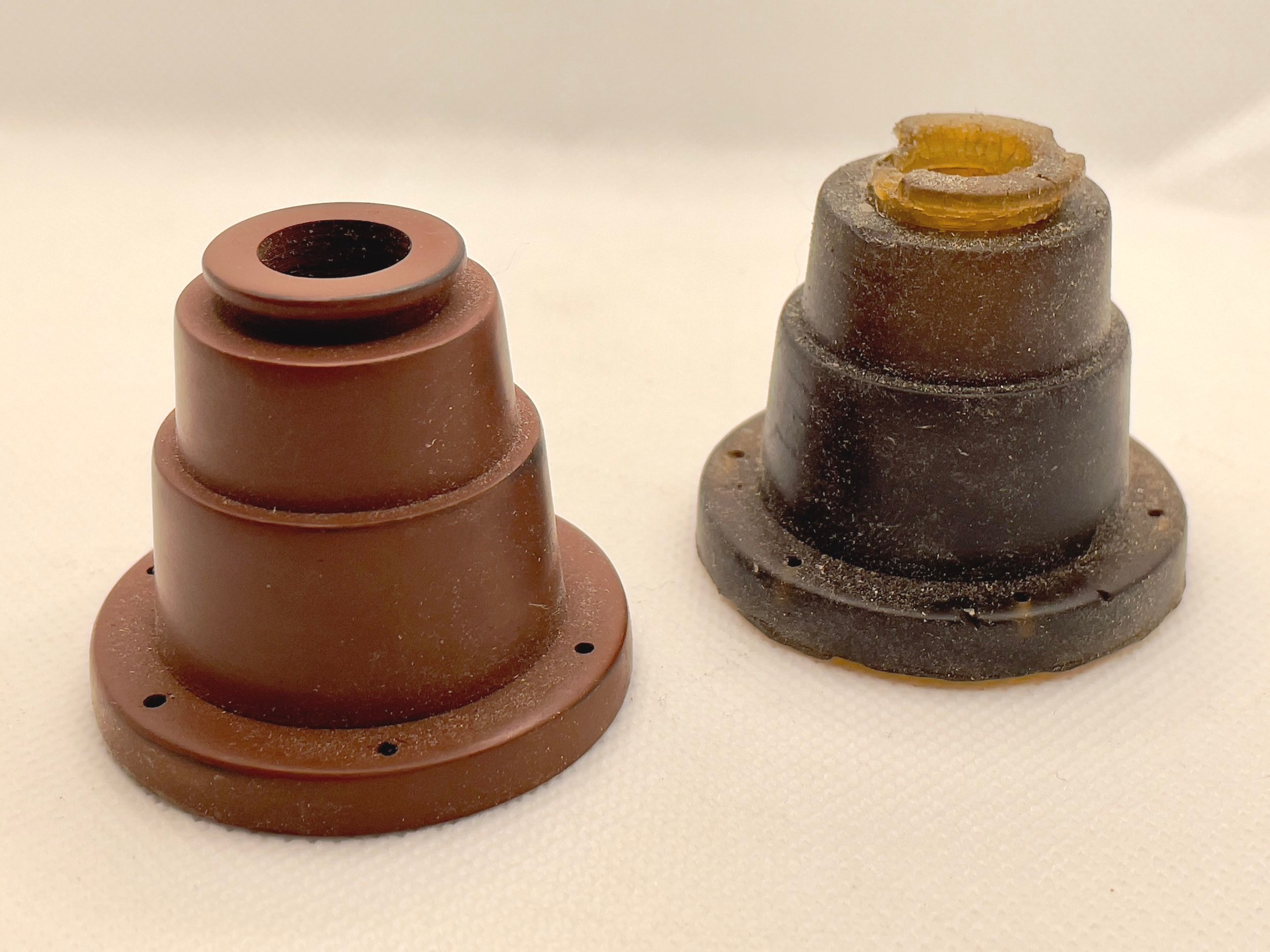
Here is what that first casting looked like without any dye and next to the original ASA print. Over a couple of days, it degraded and broke apart in some areas. I’m still not sure why this happened. I can only assume I got the mixture incorrect, but this is why you test processes when working with new materials.
The mold may look a little rough because around the edges, but molds don’t need to be pretty. I made the mold box out of Lego bricks, so there’s a fun brick pattern on the sides and the top is bumpy because it faced some rough clay holding the original connector in place.
Test Fitting the Connector
I still wanted the connector to appear to be sewn on, so my first thought was some sort of plate on the bottom that would lock into a second plate on the uniform with a thread or twist lock. A threaded pair of plates were easy to design in Fusion 360. I printed them in PETG to test the idea and temporarily attached them to the ASA print with some thread. The idea was sound, but even very thin plates (<2mm) created a noticeable gap between the uniform and connector. The connector naturally sags at a ~45° angle (more or less), so the attachment point is very much on display when the uniform is worn.
Next, I toyed with the idea of moving the second plate inside the uniform. This would involve cutting a hole in the leg but would move the connector closer to the fabric. If the hose actually connected to something, there would be a hole in the uniform, so I committed and cut a hole in my flight suit.
Still, the plate on the bottom of the connector was visible and I wasn’t completely happy with the fit. I’d have to move the threads inside the connector, too. I know I could have reduced the diameter of the plate and nested it inside the rubber connector, but I worried that the weight of the connector and inevitable yanks or tugs on the hose would eventually begin to rip the plate away from the rubber.
I returned to Fusion 360 and modified the screw plate to be a sort of core that would go inside the connector. The core gained some cut-outs that would ensure the core remained embedded in the rubber and would never slide out.

Fusion 360 Cross-section Showing the Connector (Pink) with Threaded Core (Blue) Connected to Leg Plate (Orange)
I also modified the leg plate to have thread holes so it could be sewn onto the uniform and included some clearance for waxed thread (the sort used for leatherworking) sewn through the holes on the connector. That last detail would give the connector the appearance of being sewn on without the threads offering any actual support.
I quite liked this because the screen-used uniforms you can find in pictures and on display in various places all have sagging deformed leg hose connectors. Over time, the rubber breaks down and the connectors deform around the threads. By making the threads just a cosmetic detail I’d never have to worry about something yanking the connector and ripping a thread through the rubber.
Casting and Assembly
Now I had to get the right color. The surviving connectors are now decades old, so their color isn’t a great reference. From rewatching the films and discussions around the internet, I determined the connector should be close to the same color as my flight suit (i.e., a shade of khaki brown), but getting that color was tricky.
Note: The color of the adapter changes between Ghostbusters and Ghostbusters 2. The connectors are grey in the sequel and I was very much tempted to just make a grey connector after several attempts trying to get a brown I liked.
The secret to getting close to the proper khaki-ish color was a bit of yellow dye mixed in with brown and white. I didn’t have any yellow dye, so I ran to the store to fetch a yellow Sharpie marker. I cracked it open and squeezed some of its yellow dye into the mixture.
I was on a time crunch before SiliCon and couldn’t get proper dye in time. This felt like a crazy idea, but I figured Sharpie markers are alcohol-based, so it wouldn’t cause any issues with the Econ 60. It actually worked!
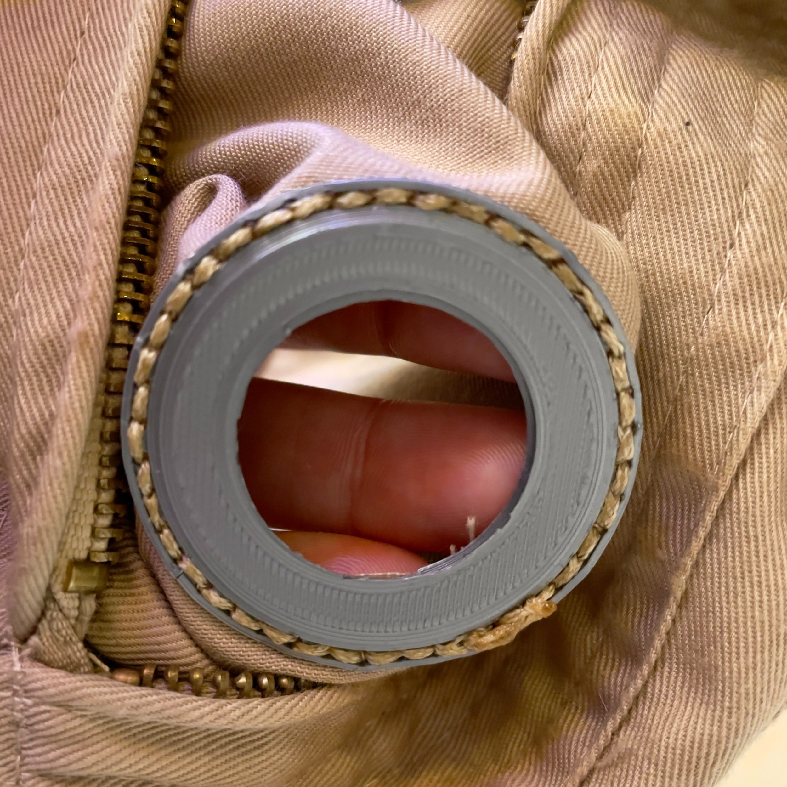
Before pouring the Econ 60 mixture, I glued a neodymium magnet into the small recess inside the PETG threaded core and then placed the core over the center post of the mold. The Econ 60 cured around the core and magnet, sealing the whole assembly inside the rubber.

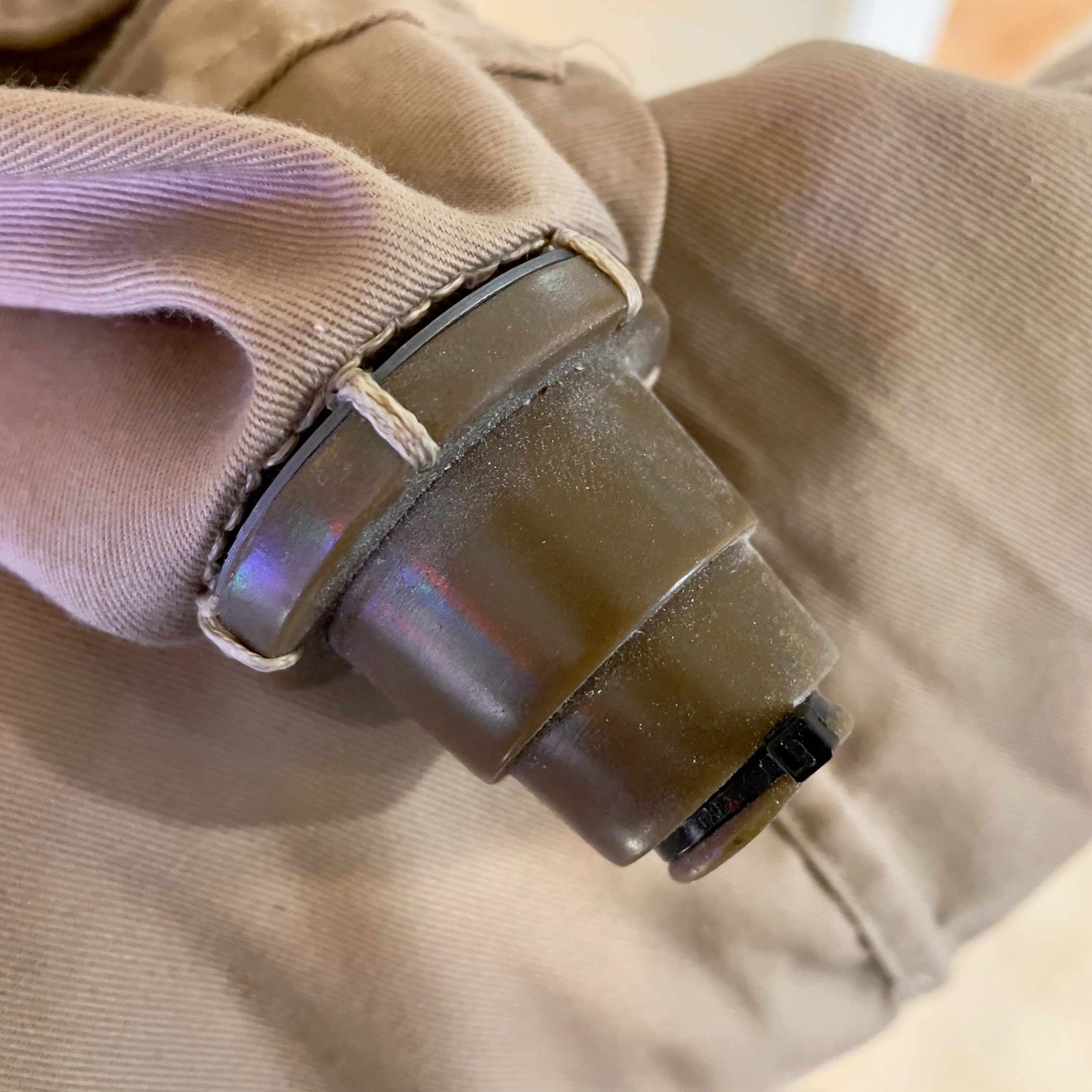
Final Leg Hose Connector with a Flush Connection to the Fabric
Securing the Leg Hose
To secure the ends of the leg hose, I created two barbed inserts that slid into either end of the hose. One insert held a second magnet and the other had a loop for a screw. The magnet end slid into the leg hose connector and stayed quite secure with a combination of magnetic force and friction. I discovered the holes in the pistol belt were perfectly sized for Chicago screws, so I used those to attach that end of the hose to my belt.

Hose Ends with Barbed Adapters for Chicago Screw and magnetic Connections
The typical ways the hose is secured to the belt usually involve cutting slits in that end and using a keyring or zip tie to attach it to the belt. That end looks slightly misshapen in the above shot because there are slits in the hose from using a keyring. I always worried the hose would get pulled and the keyring would tear through it. I’m much happier with this solution.
Real-World Testing
This setup worked really well at SiliCon 2021. The full configuration got tested when someone walked by me while I was getting a drink and snagged the hose. Everything worked perfectly! The hose connections failed as I designed them to fail and no one was tripped or taken for a ride. The one issue was the hose adapter with the Chicago screw. The screw held the adapter tight against the belt, so it was between two (mostly) rigid surfaces. When the hose pulled away from my body the adapter flexed against the screw and snapped along the layer lines.
When I got home, I re-printed it oriented sideways. Sideways isn’t an obvious orientation because round things don’t usually print well like that. In this situation, we don’t care about surface quality or maintaining a perfectly round barb because it’s a part meant to be hidden by a belt and proton pack. Making it so the layer lines would be perpendicular to the direction of force expected to be applied to the adapter was much more important. Now, if the hose is yanked and the adapter is pulled against the screw and belt it will be much less likely to break because the force is pulling against the layers.
Wrap Up
This was a fun project and I am very happy with how it turned out. I completed this about six months ago and in that time I have acquired a metal lathe. If I revisited this project in the future, I would likely take the 3D models and try turning the pieces on the lathe using aluminum and mild steel. While PETG should survive a washing machine (if I did wash the uniform, I’d wash it using cold water on a delicate cycle so PETG should survive with no issues), aluminum parts would hold up better over time and look really nice. Steel would work well for the hose inserts and remove the need for a second magnet and any worries about matching polarities.
Another potential upgrade would be replacing the threaded plates with some sort of twist-lock or an altered design that wouldn't leave an open hole in the leg when the connector was not attached. This is another reason a machined metal part would be a nice upgrade; it’d still look good as part of the uniform without the leg hose connector.
I still really like the general idea of the removable connector. If you don’t want to wear the leg hose, you can attach a substitute that acknowledges the connector should be there while also adding some sort of personal touch to your uniform. I got this idea from Bill Doran of Punished Props. I ran into Bill at KingCon 2021 while he was wearing his Ghostbusters uniform. Not a fan of the leg hose, Bill chose to sew a patch onto his leg as if he had removed the connector and patched the hole. I really enjoyed that idea and it inspired me to design a cover for when I wanted to go without the hose.
I whipped up a cover that mashed together valve designs from NASA and cosmonaut spacesuits. I couldn’t resist using some cosmonaut inspiration.
“What are you supposed to be, some kind of a cosmonaut?”

Leg Hose Connector Cover

Build Log: ACNH Happy Home Academy Plaque
Follow along as we build a customized replica of the Happy Home Academy plaque.
Nintendo recently released a big update and new content for Animal Crossing: New Horizons, so I’ve been sucked back into the game and decorating my home and island. That got me thinking it would be fun to make myself a Happy Home Academy plaque for my real home! This would be a chance to make some simple molds and have fun with cold casting.
I started with the plan to 3D print the face details, make molds with brass or gold metal powders, and laser engrave placement for everything into a wood plaque.
Photography Time
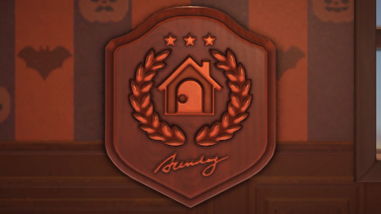
To get started, I had to snag a few screenshots. The update made this simple with a new “handheld” mode for the in-game camera phone that lets you snap photos from your character’s perspective. I placed the plaque at eye level and took a few photos to get an idea of the size of the plaque and capture the details.
Next, I needed to nail down a few details, like the measurements and what the signature at the bottom is supposed to be. The measurements were easy. The plaque seemed to be about the size of my character’s head, so I roughly measured my own head with a tape and figured the plaque would be about 9.5” tall. I opened the screenshot in Photoshop to resize the image to match. To my surprise, the screenshot was already about the right size. I made a box that was 9.5” x 8” and the plaque was only slightly smaller. I assumed the plaque would be as thick as the plaques I had in on-hand, about 16.75mm.

Plaque with the Properly Sized Bounding Box
The text at the bottom was more difficult to understand. People of the internet have tried to determine what it is and there are two dominant theories. One theory is the text is “Academy,” but the cursive lettering doesn’t match very well. The cursive does appear to match “Sunday,” the day you receive your HHA grade and applicable plaque in the game.
I wasn’t happy with either of these options. A real plaque would probably include information-e.g., the HHA rank, score, date, or the recipient’s name. I chose to redesign the bottom to include my name or a space for a metal plate.
Photo to Vector
I used Adobe Illustrator to trace the plaque’s shape and face details before importing the SVG into Fusion 360. I did it this way so I could draw the inner shape of the plaque and then use Illustrator’s Offset Path tool to create the outer edge. I found this easier than trying to do everything in Fusion 360.
I also added a 10” x 10” bounding box so I could be certain the design was the correct size after importing it for the laser or Fusion 360.
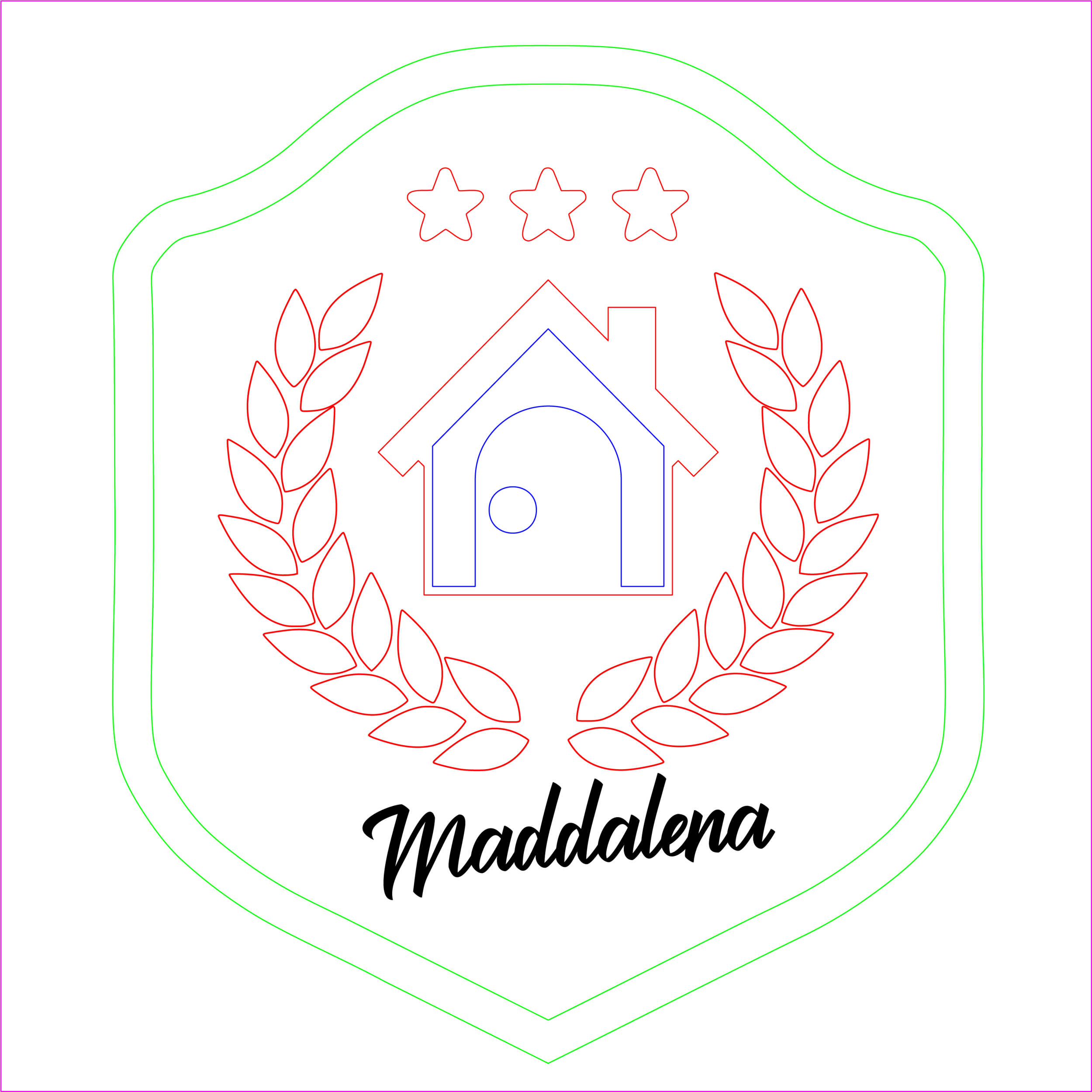
Near Final-but Flawed-Vector Design
I added my name at the bottom as a placeholder while I determined what I wanted to put there. The SVG was almost done, but there was an issue: the outline of the plaque was too complex.
Sometimes you import an SVG and Fusion 360 will choke the moment you ask it to extrude a section. In my experience, this is often caused by very complex vectors. My outline of the plaque’s shape was complex enough to make it impossible to work with inside Fusion 360. I used Illustrator’s Simplify tool to reduce the number of points.
Tip: If you highlight your vector graphic and have tons of little points, Illustrator can simplify the design. Select your graphic (or the complex paths) and then go to Object menu, select Path, and then the Simplify… option.
Remember, simplifying does tend to round corners. I had to go back and readjust the above version because I simplified everything instead of just the plaque outlines. That was mostly fine but it decimated some curves and corners that were really necessary for making this a 3D model. For example, the simplification made the stars ever so slightly non-uniform and rounded the interior corners. They looked fine at a glance, but the geometry didn’t work for what I wanted to do in Fusion 360 (e.g., tapering the shapes).
Taking 2D to 3D
After some tweaks, the SVG was done and provided everything I needed to make the 3D model. All I had to do was import it and extrude the sketch elements, but first I had to make sure it imported with the correct scale! I follow AutoDesk’s suggestions for how to do this.
First, I imported the SVG, placed it, and measured the lines of my bounding box. They were supposed to be 254mm (10”), but measured at 190.503mm. When divided, these measurements showed the SVG needed to be scaled 1.33x (actually 1.333312336288667… but one can be too precise). I removed the SVG and placed it again with that scale. That gave me a properly sized sketch.
First, I extruded the whole sketch to make the base plaque. I extruded everything -16.75mm. The negative number made it so the body extruded below my sketch and the sketch elements remained on the top face of the new body. Little things like this helped me manage the design and keep everything straight in my head.
Then I cut out the outer area of the plaque and added a fillet where the front of the plaque met the back. This created face of the plaque and the curved dip down to the base.
In case I ever wanted to 3D print a whole plaque, I cut 1mm slots in the plaque body for all of the face details and then extruded all of the details to be 3mm thick. Each piece would extend 2mm from the face of the plaque.
The stars are curved on the game model, so I tapered the extrusion to match. To make sure they wouldn’t curve below the surface of the plaque, I extruded the stars to be 2mm with the taper and then extruded the bottom of each star 1mm into their recesses.

The Final Render of the Plaque
This way the pieces could be printed separately and dropped into the slots in the plaque. This also made sure the pieces would fit properly into engraved wood.
The plaque could be easily printed in multiple colors using a basic color swap at 16.75mm or printed separately and assembled with a little glue.
At this point, pause and appreciate that a 3D model became a 2D picture, a 2D vector, and then became a 3D model once more. Prop making can be funny.
Testing the Models

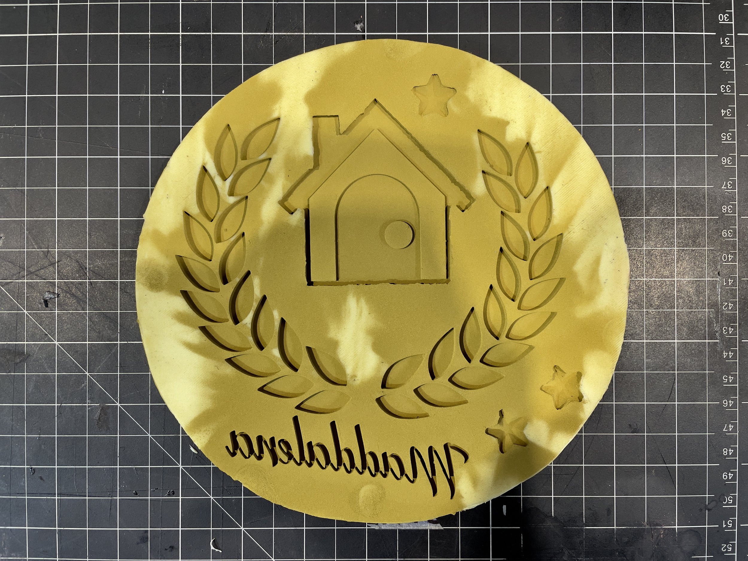
Engraving and Fit Test with an Initial Version of the Laurels
I printed the pieces in resin to capture the sharp corners of the house and reduce the prep work for the molds. I printed all of the laurel leaves individually. I could have printed and molded just one, but I wanted to make a gang mold (a mold that can create multiple copies at once). The idea was to be able to cast an entire plaque with one resin pour.
As discussed in Printing Props, I did a test assembly before proceeding. First, I found a shield-style plaque on Amazon for $12. I couldn’t find one that matched the shorter (kind of squished) shield of the in-game model, but the one I found looked good. I only cared about the dimensions being close to my design so I could test engraving everything and see how it all looked.
It would have been awful to have created a custom plaque out of a nice hardwood, engraved it, and then learned it didn’t work with the 3D printed pieces!
I prepared the SVG for the laser by checking everything against a centered line. “Measure twice; cut once” applies to vector files and lasers, too! Sure enough, I learned a few things had drifted slightly out of whack during editing, so I re-centered everything.
The printed pieces fit well inside the engraved areas. The fit wasn’t perfect, but there were some knots or sappy sections of wood that hadn’t burned evenly. I felt alright proceeding with the plan. My chief concern at this point was material shrinkage. The final resin pieces could shrink enough to affect their fit. All resins do not shrink equally or 100% consistently.
If I had a CNC machine, I would have used that instead of the laser. A CNC would be the best tool for this job, really. It would be able to cut and shape a plaque out of wood stock and create the recesses for the face pieces.
The resin I tend to use (Prusament and Siraya Tech) seem to shrink about the same as Smooth-On’s Smooth-Cast 326, so I felt confident the final pieces would work. I’d have the test engraving to do another fit test before trying to create my final plaque. If the pieces didn’t fit, I could scale the vector file for the laser to account for shrinkage before the final. Again, it’s important to test everything before rushing ahead using more expensive materials.
Inspiration Strikes
I had set out to make a wood plaque, but I had some new tools for foamsmithing and decided to try making the plaque out of EVA foam. The in-game plaque looks like nicely finished wood, but I thought it would be fun to make a plaque that embellished the general cartoonish nature of Animal Crossing. I decided to make the plaque out of EVA foam and carve wood grain.
I returned to the SVG and added an offset path to the interior of the plaque (-12.7mm). Then I cut out three pieces of 6mm EVA foam:
1 x Back piece
1 x Middle piece with the center cut-out
1 x Front face
I dropped in a laser-cut piece of 6mm hardboard into the center to reinforce the foam and add some rigidity. That is why I used two 6mm pieces for the back instead one 10mm piece of foam. The hardboard core also provided something that could take a screw for a sawtooth hanger or something similar, if I ever wanted that.
You may notice 3 * 6 does not equal the planned 16.75mm thickness, but the plaque felt right in my hands.

EVA Foam Base with Hardboard Insert and Score Line to Line-up Top Layer
I used SKS Props HD Foam. It’s generally awesome stuff, but I have found it works the best of any EVA foam I have tried with a laser. Once I had everything cut and engraved, I glued it together with Barge contact cement.
To create the curved transition between the top and bottom, I filled in the seams with Gap Filla by Prop Monkey and used a rounded silicone make-up brush to create a smooth curve. Once that dried, I got to use a new tool: a 45° beveling tool for my rotary tool made by Arcane Armoury. The side view of the in-game model looked like it was curved from the front face to the back, so I beveled all of the edges and then smoothed the corners.
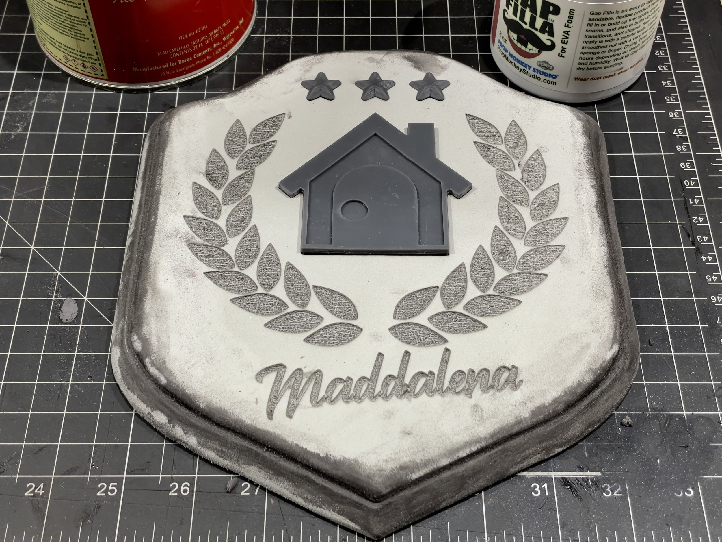
A laser can engrave EVA foam so well that it creates recesses that are as good as a CNC. It’s just foam instead of wood, so I’d have to do some additional work to sell it as a wood plaque from the world of Animal Crossing. The downside of the laser engraving is the engraved surfaces of the foam are very much not smooth, so if it’s exposed as part of a prop you have to fill it with something like foam clay, Gap Filla, or another body filler. In this case, the rough surface worked in my favor because it provided something for the glue to grip for a strong bond later.
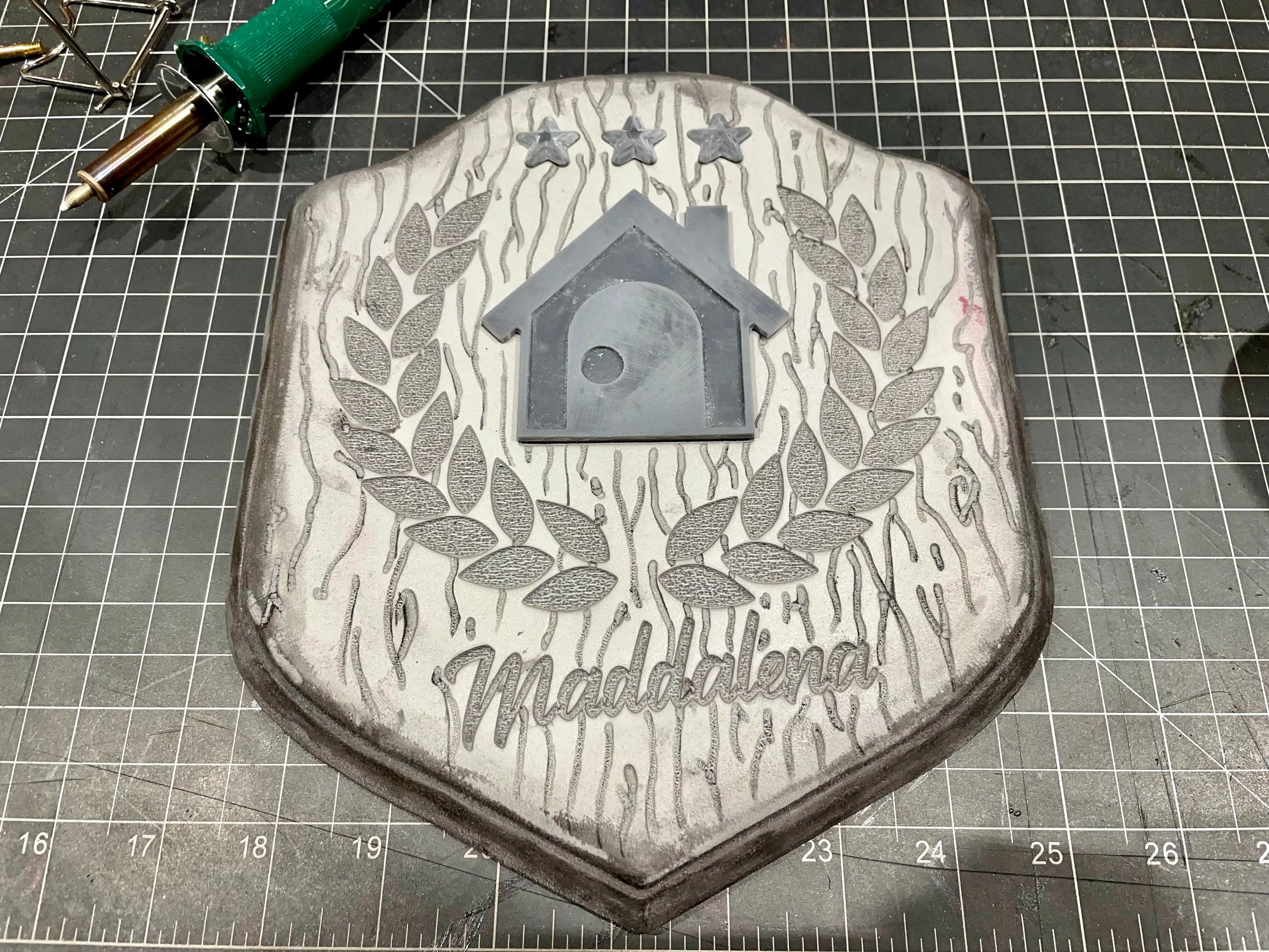
I carved in wood grain using a wood-burning tool. I had always drawn a design, scored it with a craft knife, and opened the lines with a heat gun, but I really wanted to try this method. I used a blunt tip to trace the grain and create some even valleys, "knots, and small holes. Once finished, I heat sealed the foam and coated everything in Plasti Dip.
Making the Molds
I considered how I would have to glue down 36 laurel leaves, decided that sounded awful, and came up with a 3D printed solution. I bought an 8” cardboard tube from the hardware store (the sort meant for cement posts). When placed over the foam plaque, the tube covered the face details with ample room on the sides, so I modeled an 8” circle below the laurels and joined the bodies. I printed the whole thing in ASA and enabled ironing on the topmost surfaces (the front of the leaves) in my slicer.
Ironing smoothed the most-and most important-surfaces of the leaves and letters, so I had to do minimal clean-up. I didn’t bother sanding the sides of anything. That meant some layer lines remained visible from the side, but they’d be difficult to see even up close on the finished plaque. There was no reason to spend time sanding the sides of 36 leaves when only one side of 18 leaves (the outside) would really ever be seen. Not to mention, 2mm is very small, so you’d have to get really close to see any visible lines in the castings.
This gave me an 8” circle on which the cardboard tube could sit. Voila! A mold box. Hot glue sealed the edges and attached the house and stars printed in resin. Then I poured Mold Max 29NV into the box and let it sit overnight.
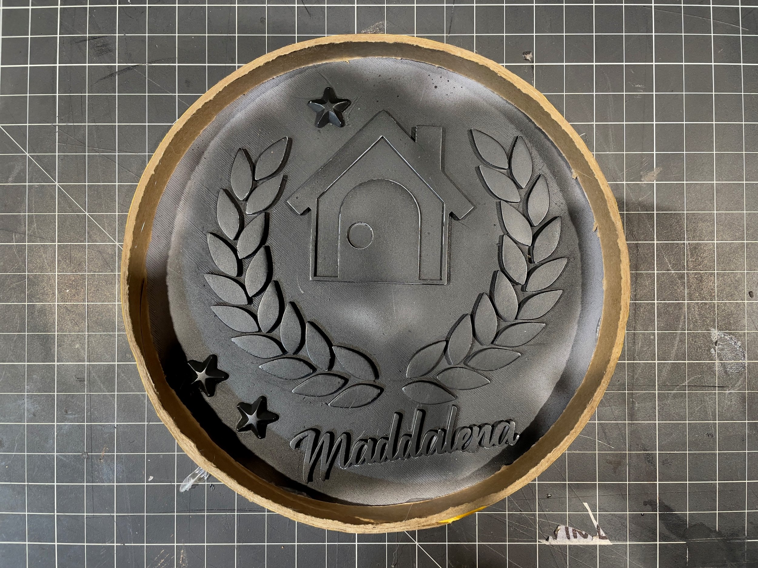
The mold came out well. My one concern was some of the walls were thinner than I would have liked because I didn’t bother to adjust the layout of the laurels. In reality, the laurels were fine, but the name was much more problematic.
I dusted the mold with brass powder and mixed equal parts brass powder and Smooth-Cast 326 parts A and B. I chose brass because it’s what I had available and polished brass fit the bill as much as antique gold. As an alternative, I could have used some gold leaf, a technique I have wanted to explore for some time. I thought applying leaf to so many little bits would have been really tedious.
I let the mold sit overnight to allow the resin to fully harden. The pieces were only 3mm thick and thinner pieces take longer to completely cure. Once de-molded, I had to clean up the back of each piece.
I made an open mold, so I had to pour resin slowly and try to cut it off before any of the cavities overflowed. Some of the pieces got a little too much resin and were slightly thicker and domed on the back and most pieces had a small amount of flashing on the edges. My rotary tool made quick work of these features.
The same rotary tool buffed the brass powder coating with an abrasive buffing wheel. I used a black pad, about 400 grit, and let the speed of the rotary tool do the work while I lightly touched the surface of the parts. I didn’t want to rip through the powdered surface but buffing with steel wool might have applied too much pressure to high spots and edges on these little fiddly pieces. The powdered coating would be much shinier and provide a nicer finish than the powder mixed into the resin, as long as I didn’t rub it away.
Troubleshooting
My initial casting attempts were disastrous. For my first try, I dusted the mold and poured in a resin mixture that only included the excess brass powder I shook out of the mold. When the resin kicked, there was a severe reaction where the resin met the brass powder and silicone. The castings looked like swiss cheese.

Store Bought Silicone (Left) vs. Mold Max 29NV (Right)
I encountered this sort of thing earlier this year with several different Mold Max 29NV molds and I have reached out to Smooth-On to determine the reason, but I don’t have an explanation yet.
The issue looked like severe bubbles caused by moisture, but I tested the same process with one of Evil Ted’s silicone molds purchased from a craft store. I mixed a new batch of resin, dusted both molds with brass powder, and poured. The same reaction occurred with my mold while the Evil Ted casting turned out fine.
I resolved this by following Smooth-On’s guide to cold casting and mixed an equal part of brass powder in with parts A and B (1 Tbsp of each). Following directions seems like an obvious solution, but I have avoided this in the past to save the expensive metallic powders. However, I made those molds with Mold Max 30, so all signs point to Mold Max 29NV causing a funny reaction when cold casting powders are involved.
Final Assembly
Before I could attach the individual pieces, I had to paint the plaque. I wanted to match the reddish color of the in-game model but personally preferred a darker wood. I used Liquitex heavy body acrylic burnt umber (sort of a dark or walnut brown) as the base and got it into all the details. Then I applied more reddish browns, raw and burnt sienna, over the darker brown base. I used a light touch and some dry brushing techniques and let the surface texture pull the paint off the brush.
I finished the paint job with a few highlight passes with the burnt sienna. This pass gave the edges and high spots a more prominent reddish color. The last step was a top-coat. The in-game model is very glossy, so I tested some high-gloss finishes on scrap pieces.
Smooth-On recommends using a semi-gloss acrylic coat of some kind to protect the metallic finish from oxidation, so I paused to use some of the failed castings and foam cut-offs to test what it would look like if I coated everything in a gloss top-coat.
I didn’t want to go through all of this trouble for a real metallic finish only to fumble the top coat and make it all look like a bad paint job.
I settled on applying Alclad Aqua Gloss to the plaque alone. I applied several coats until I was happy with the overall shine. Then I inserted each of the pieces with a bit of Bob Smith’s Maxi-Cure CA glue. The Maxi-Cure is thicker than the Insta-Cure that I usual use and stayed where I put it while I lined up each piece.
Before I inserted the house and stars, I added some dry-brushed highlights with Liquitex heavy body acrylic iridescent bright gold. The iridescent bright paints are thin and meant to be mixed with other paints or used to add a subtle shine. The effect was indeed subtle but made a big difference. It really helped sell the polished brass as an antique gold. The laurels got the same treatment after they were glued down.

Dry-brushing Gold onto the Brass
At this stage, I learned the name plate was too fragile. I managed not to break it while sanding, cleaning, and polishing the piece, but it eventually broke when it fell off during a test fit. The first failed casting had ruined one of the thinner walls, so making more would have been more painful than using one of the resin prints I had.

Some Thinner Walls Had Some Tiny Bubbles or Gaps that Made Those Walls Very Weak and Hurt the Surface Quality
A backup print replaced the broken piece. I painted it using Alclad II Polished Brass lacquer so it would match other pieces. I hit the edges with a little Pale Gold lacquer and really liked the results. When the light hit the painted surfaces from the side the name shined a brighter gold color but still matched the brass-coated pieces when looked at head-on.
Sunday Arrives
The next day the paint was dry and the name was ready to be attached. It was a Thursday, but I finally had my finished plaque. However, it would be a few more days until the gold sawtooth hangers I ordered would arrive.
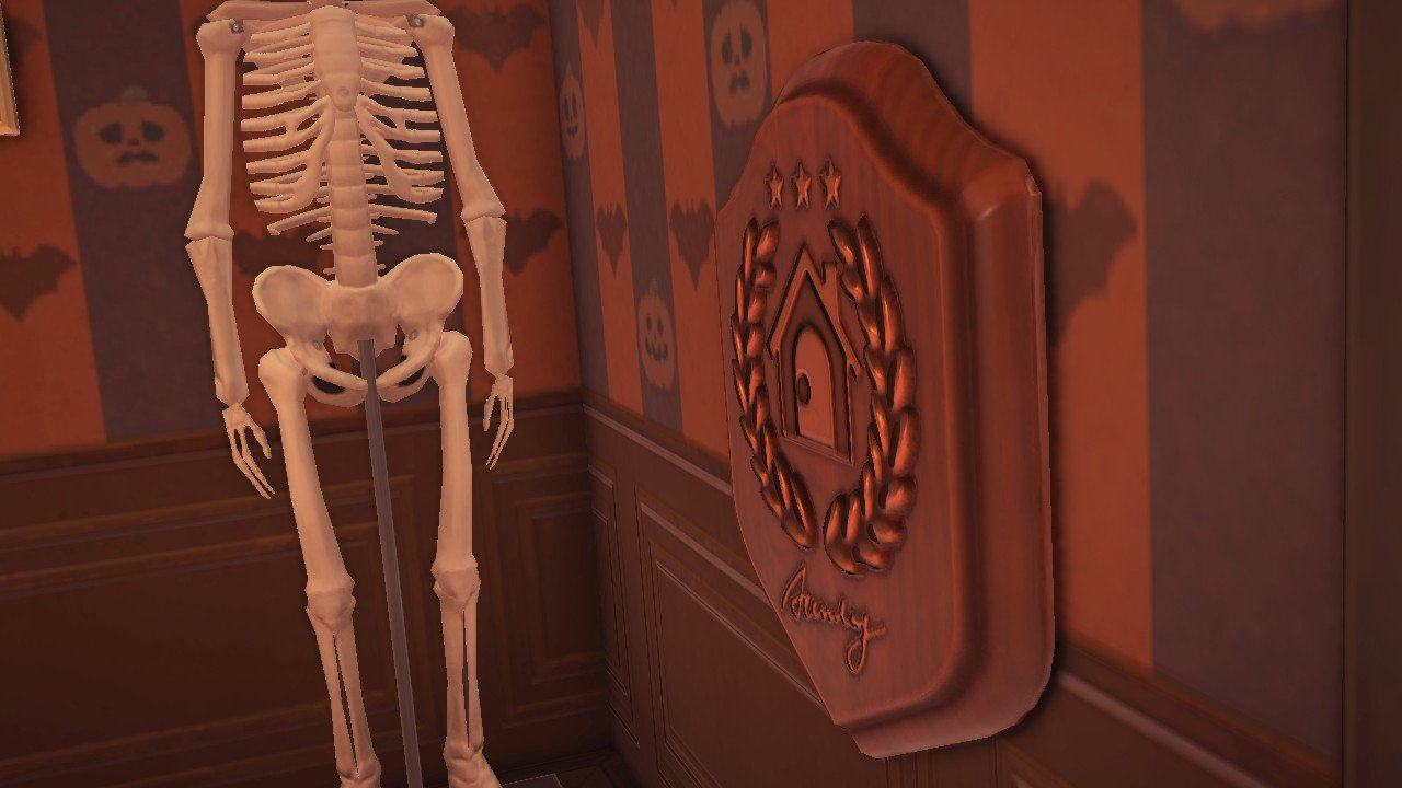
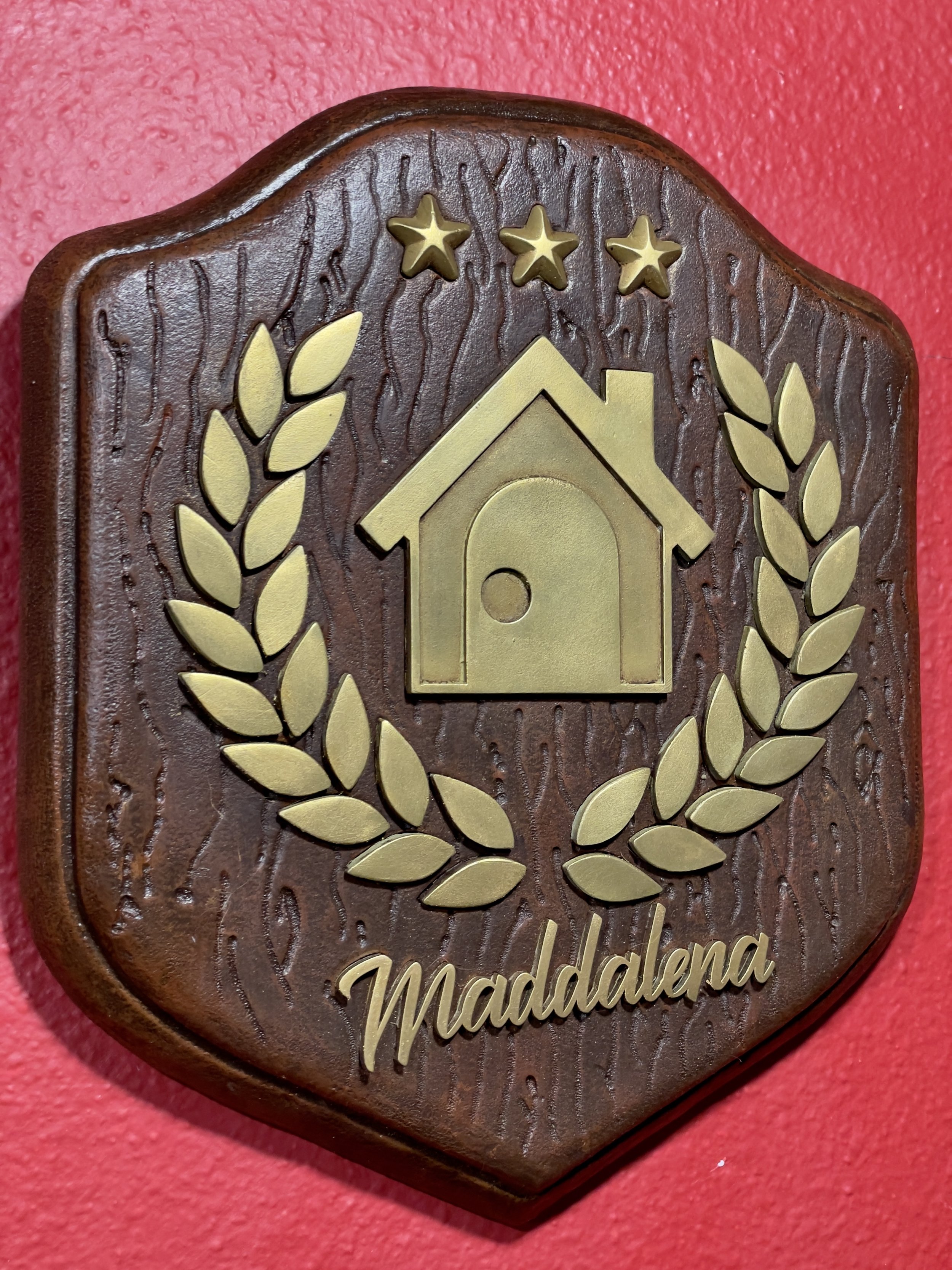
The hangers arrived on Saturday. I attached one to the back of the plaque with 8.6mm gold wood screws. For the fun of it, I left it alone until the next day. As in Animal Crossing, when Sunday morning arrived, I collected my plaque and put it on display.

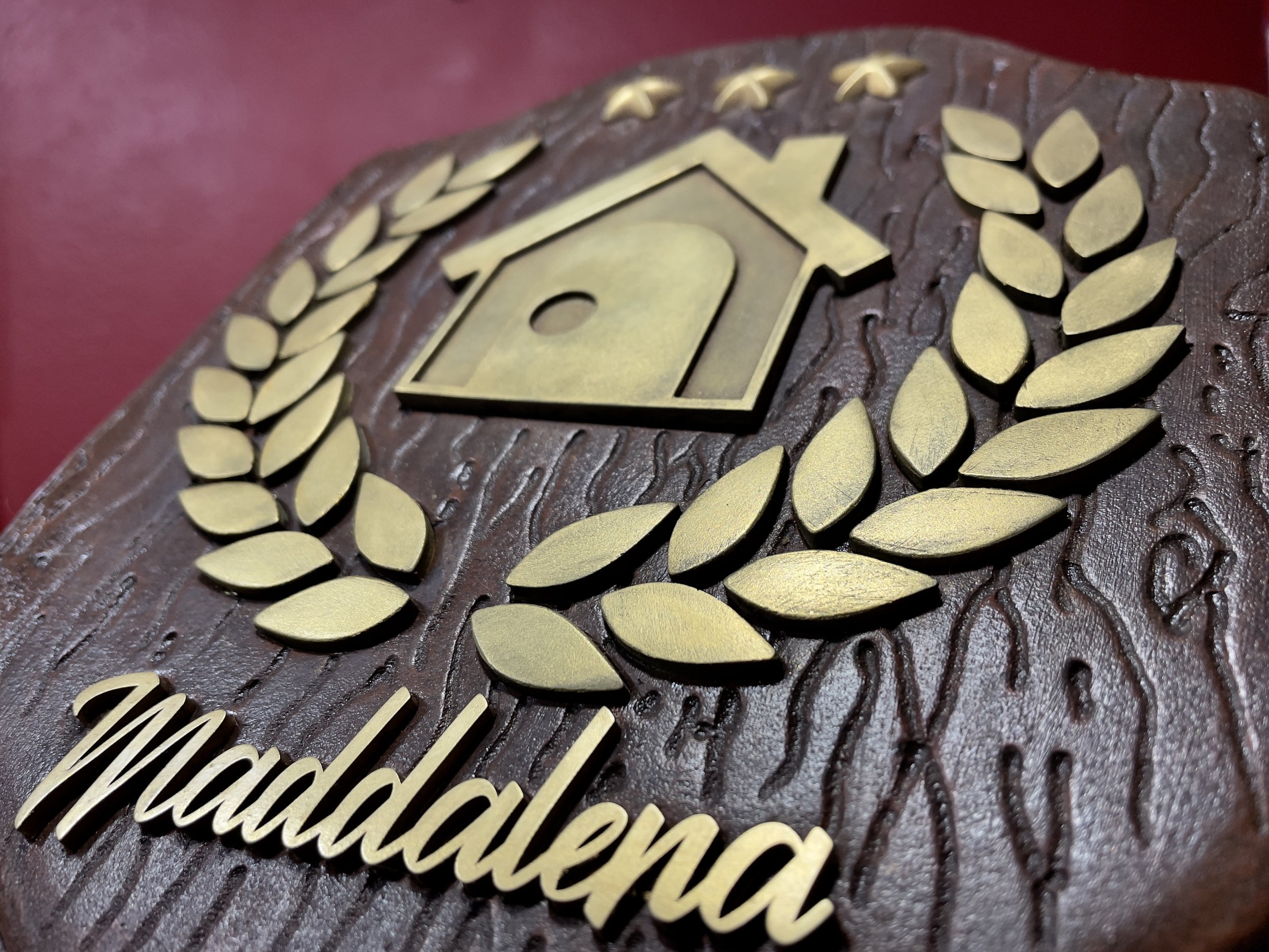
The Final Plaque Before Any Modifications
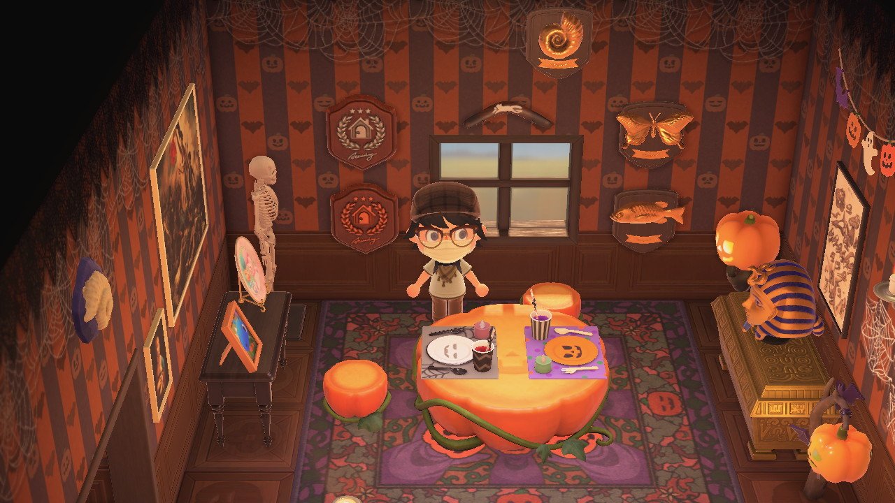
This was a fun project. I really enjoyed experimenting with engraving EVA foam to accept resin inserts. I expect I’ll do this a lot more in the future to hide seams or give them a different look.
I wasn’t completely satisfied with the brass powder and might revisit this project down the road if I ever find myself with some gold powder or leaf. The problem was the brass powder lost some of its brilliance and shine once the plaque was on a wall and out of direct light. The beauty of making molds is I can jump back into this project at any time and have a set of new parts with just a few minutes of work!
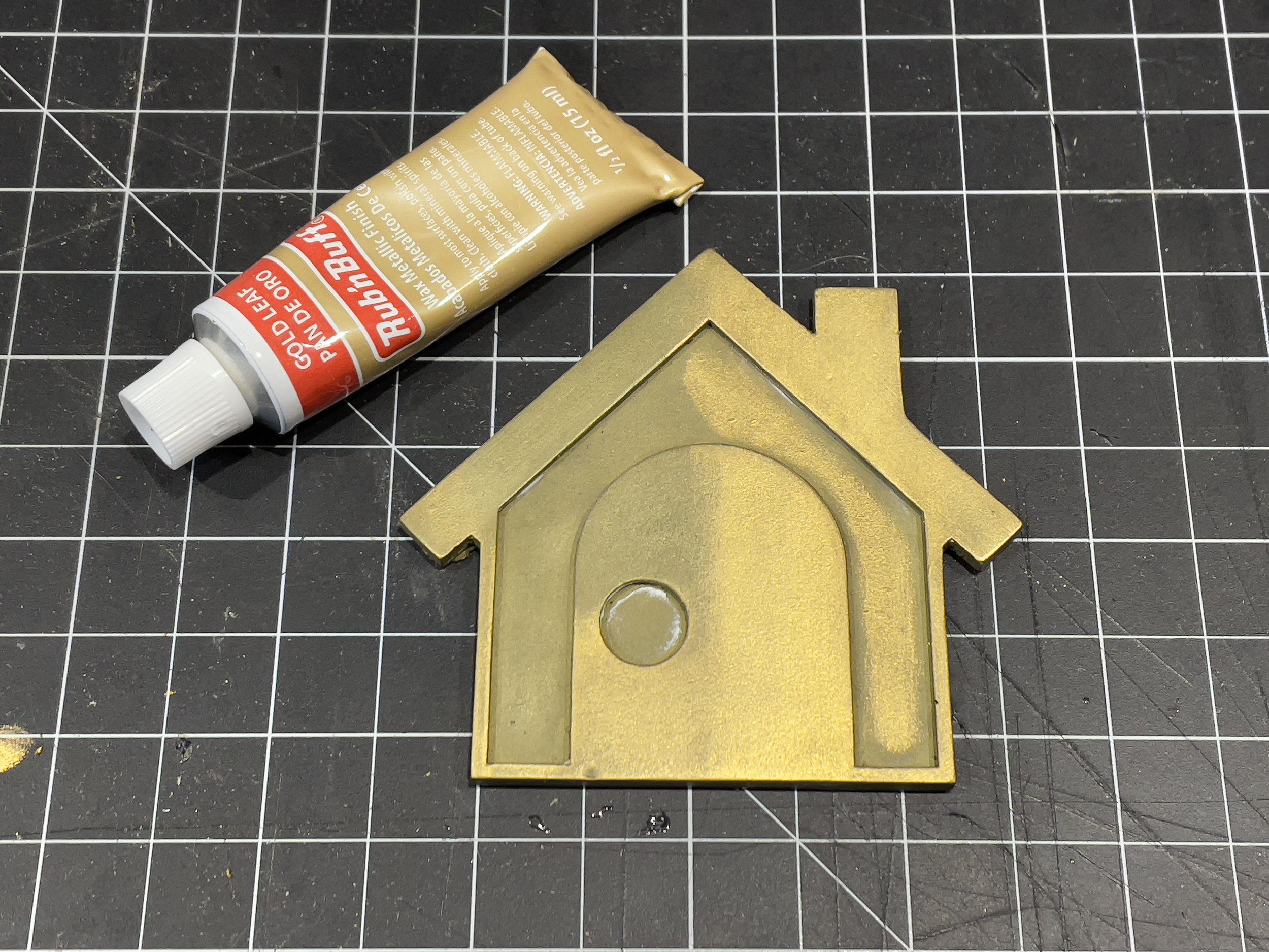
In the meantime, I picked up some gold leaf Rub ‘n Buff metallic wax. This stuff is great for adding metallic accents to the edges and details of props. I’ve had the same tube of silver Rub ‘n Buff for almost five years and I’ve used it on dozens of projects. I almost never use it for its usual intended purpose, completely covering something to make it look like metal. It’s often advertised with examples that show it covering picture frames and various small items to transform wood or plastic into something that looks like metal. I decided to try that with the resin pieces. I had plenty of bad castings to test with, so I started there before buffing the final pieces.
Testing Run ‘n Buff Application Ideas
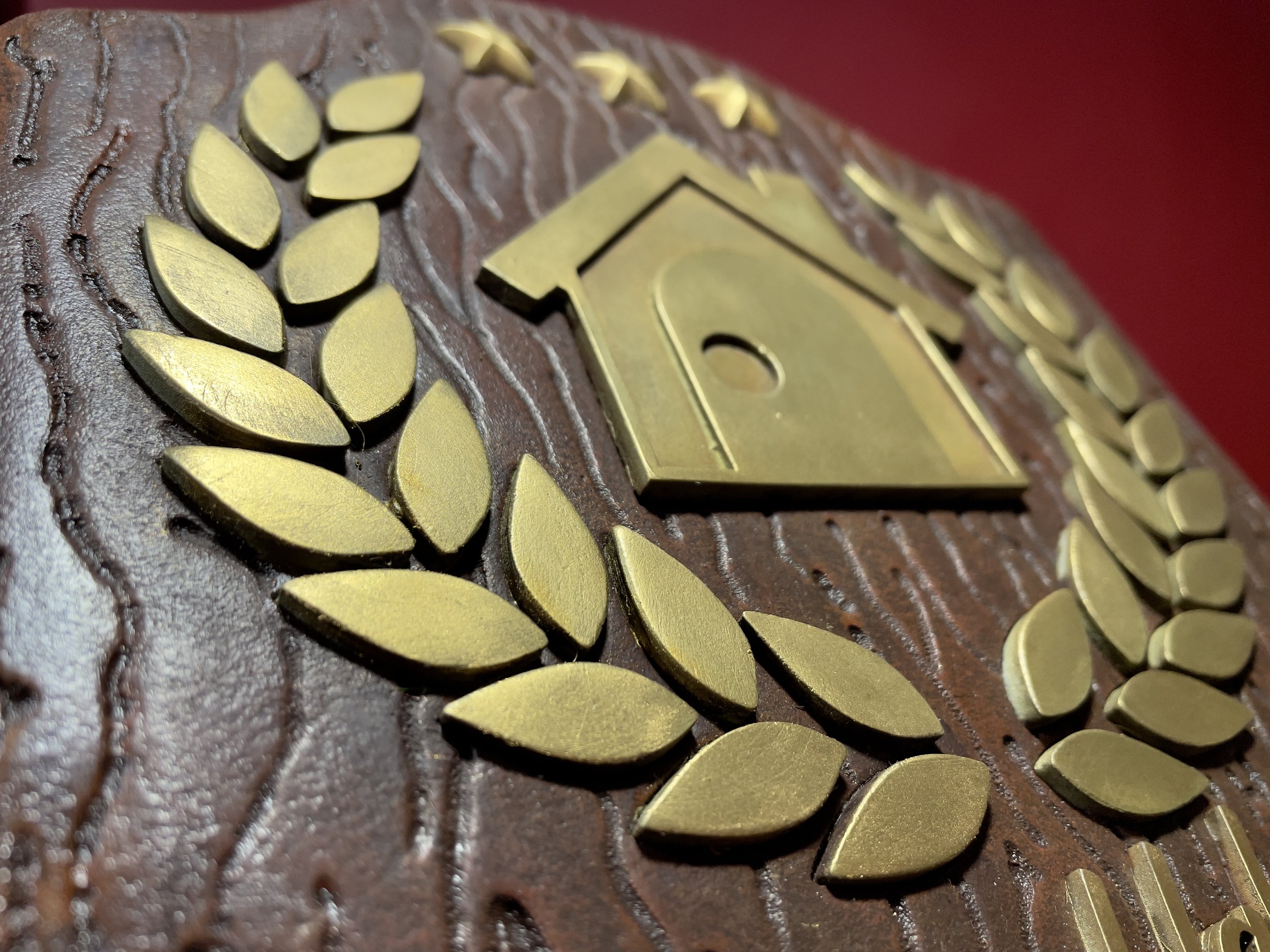
I used a soft cloth and a very light touch to add a thin layer of wax to the edges and high spots of the face details. The buffing wheel created an uneven surface on the resin parts. The scratches weren’t deep, but just enough to create texture. The light application didn’t get the wax into any scratches and I avoided applying it to anything below the top surface (e.g., inside the house). This process left areas where the brass powder was still visible and made everything look like aged antique gold that had been polished on the surface.
I was much happier with these results. It wasn’t exactly what I had set out to do, but they led to more experimentation. The mix of brass powder, iridescent bright gold paint, and gold leaf wax added some complexity to the resin pieces that really shines in person (pun intended).

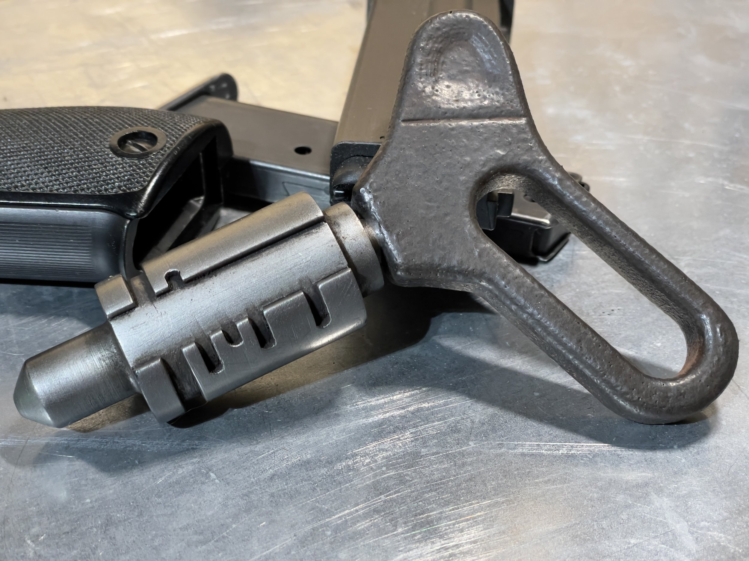
Build Log: Cowboy Bebop Zipcraft Keys
Follow along as I build a zipcraft key from Cowboy Bebop.
Hey Space Cowboy, did you lose your keys?
To prepare for the upcoming live-action Cowboy Bebop series, I restarted the anime and noticed a neat item just a few minutes into the first episode: Spike’s zipcraft key. The key appears five minutes into the first episode in a nice close-up shot. The keys appear later but are less detailed and drawn as solid cylinders. In this early shot, the key looks great and got me wanting to make one. It was a fun, quick build!
If you just want to dive in and make one yourself, the designs discussed below are available for free! You can download them from GitHub or PrusaPrinters.
The (Bounty) Hunt for References
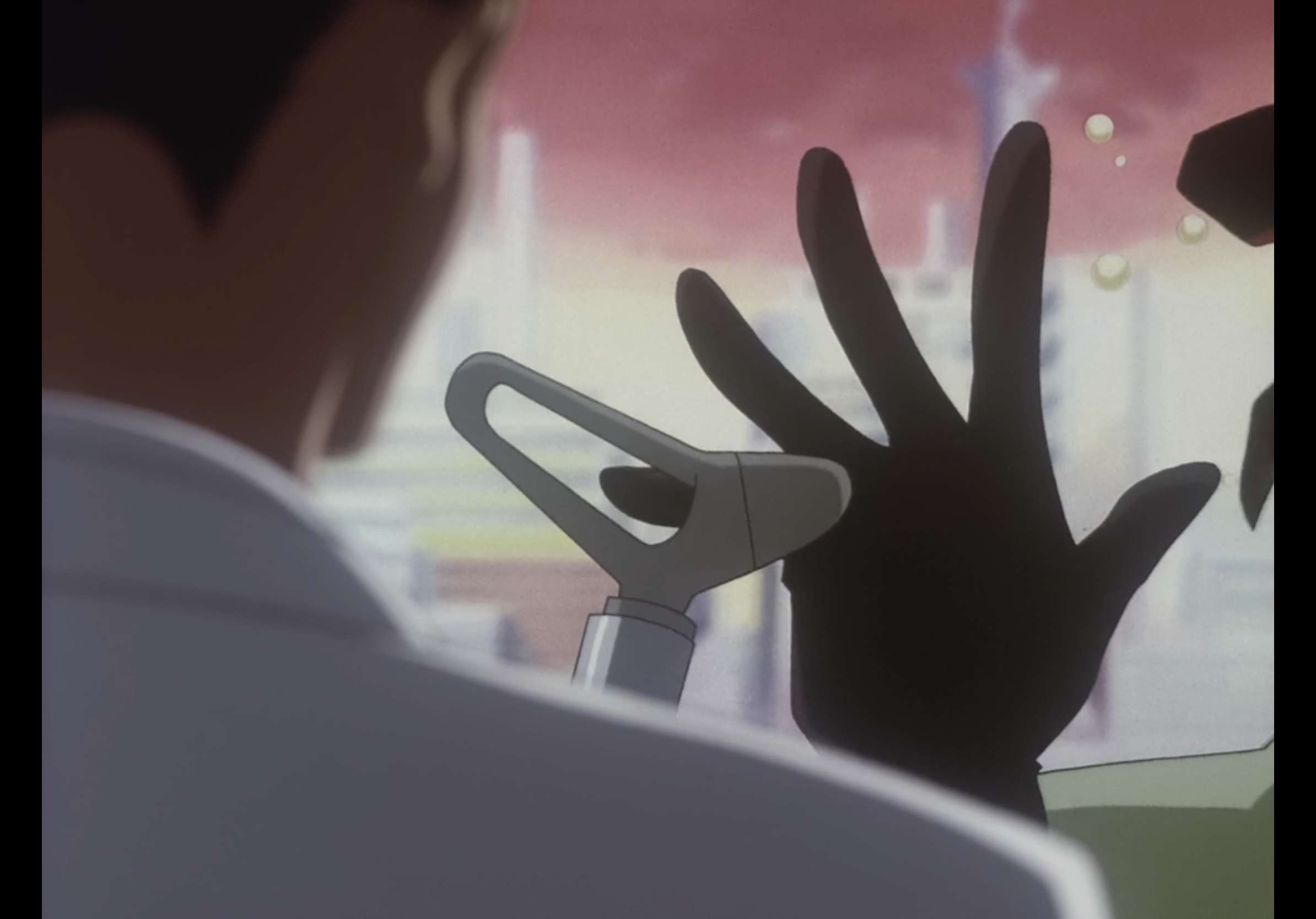
First, I had to collect some reference images. The full key is visible at 5:27 in Asteriod Blues as Spike engages his zipcraft:

Slightly Skewed, But a Well-Detailed Shot That Shows Good Proportions and Scale
The handle is slightly obscured, but this is an otherwise near-perfect reference. The key is angled just enough to show the details near the handle while not distorting the perspective too much, so we have a rough idea of the length of the key, and Spike’s hand provides a starting point for sizing the image. The image also shows only one side of the cylinder is keyed or notched. A moment later at 5:28, Spike turns the fully-inserted key to show the other side is notchless.
The show also provides a head-on shot of the key handle which gave me everything else I needed. In episode 5, Ballad of Fallen Angels, Faye Valentine tosses her key to a valet at 6:31. The key handle looks slightly longer and more angular than Spike’s, but the show’s repeated use of this design suggests this general shape is shared by different keys.
While Less Detailed, This View Shows a Groove in the Handle Covered by Spike’s Hand in the Other Shot
The scene also shows the full key, but it’s much less detailed, appearing to just be made of some stepped cylinders. Faye’s key looks similar to Spike’s, so this is a great reference for the shape of the handle. However, Faye is smaller than Spike and the key doesn’t seem any bigger compared to her hand. It’s likely no one bothered to consider that during animation because it doesn’t matter to the show. I chose to size the key to Spike’s hand-i.e., size it to an average hand size for a 6’ 1” man.
Sizing it Up
To get the right size, I opened the screenshot in Photoshop, but I could have used a free program like Inkscape. Anything that can scale images and draw a box would have worked.
I held my thumb in the same position as Spike and grabbed some rough measurements using digital calipers. I made a box that was the size of my thumb and scaled the reference image layer to about 33.82%. Once Spike’s thumb fit inside the box I rotated the image to straighten the key. The key in the image fit inside a box about 137.94mm x 85.73mm or 5.43” x 3.37”. That felt good enough to begin modeling, so into Fusion 360 it went.
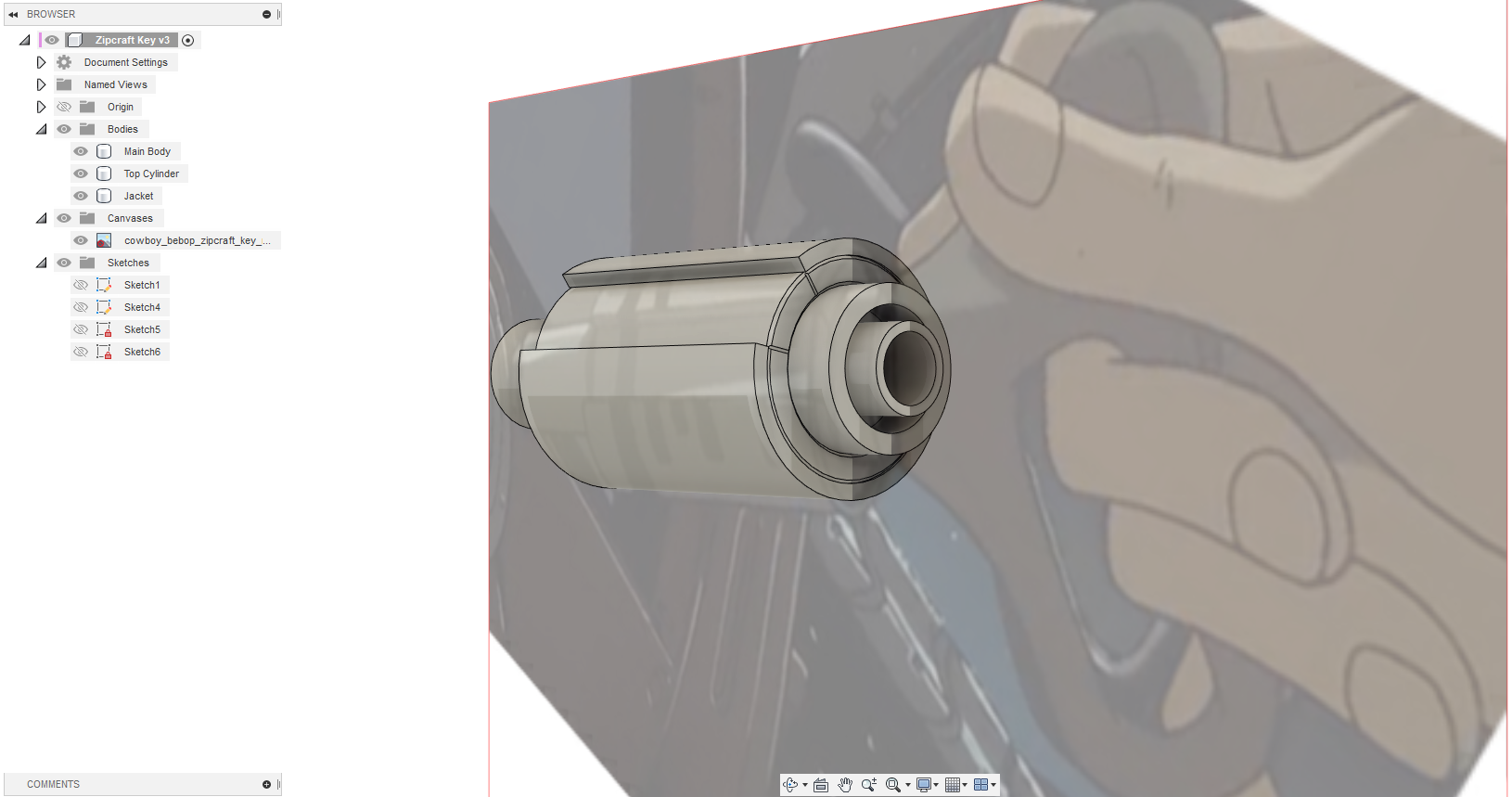
The scaled and rotated image went into Fusion 360 as a canvas I could draw upon. I lined up the canvas as best I could to help me sketch some rough dimensions. After accounting for the angled perspective, I had a profile I thought looked appropriately sized.

Rough Sketch of the Top Half of the Key’s Profile
I wanted this to be an easy model for anyone to print using FDM or resin printers, so I had to make some choices here.
I started by making the key body (the big cylinder and the skinnier, chamfered cylinder) its own body using the Revolve tool. Next, I made a sketch on the cylinder’s top flat surface to draw the notch and top details. These top details suggested the key would be assembled from multiple pieces and sanding inside the keyed notches could be a pain, so I decided to make the main body two separate pieces: the outer keyed jacket and the inner cylinder.
I cut the V-shaped grooves into the main cylinder using pipe forms, added some chamfers to accentuate the seams a tad (and help with ‘elephant foot’ issues on FDM printers), and made the top cylinder for the handle to connect. I made it so this last cylinder 1.2mm taller to fit into a 1.2mm deep cut-out in the main body. This would help with gluing it into place later.
This separation served several purposes:
Fewer supports would be needed to print the main body on an FDM printer
What supports would be necessary would only touch surfaces that would be covered by the handle assembly
The final product would look much more like separate pieces because the seams would be real
The rod/cylinder for the handle (~11mm wide) looked like it fit into a wider hole about 15mm wide, so I added this feature to the top cylinder. I also cut an 8mm hole through the entire key assembly to fit a brass rod. I had some 8mm x 100mm brass rods that came in a set I bought when I needed some smaller rods for another project. I rarely have a need for 8mm rods and one of them running through the key would reinforce the handle and add some nice heft to the final prop.
Here was the final-ish rough key body:
Taking Stock of the Progress
Getting a Handle on the Design
I imported the screenshot of Faye’s key into Fusion 360 and scaled it to match Spike’s key handle. Unfortunately, the keys were a poor match. Faye’s key had a slighter handle with a finger hole that narrowed more sharply. Enough of Spike’s handle was visible to use the episode one reference for the sketch and Faye’s key as a guide for some additional details.

Comparing Faye’s and Spike’s Key Handles
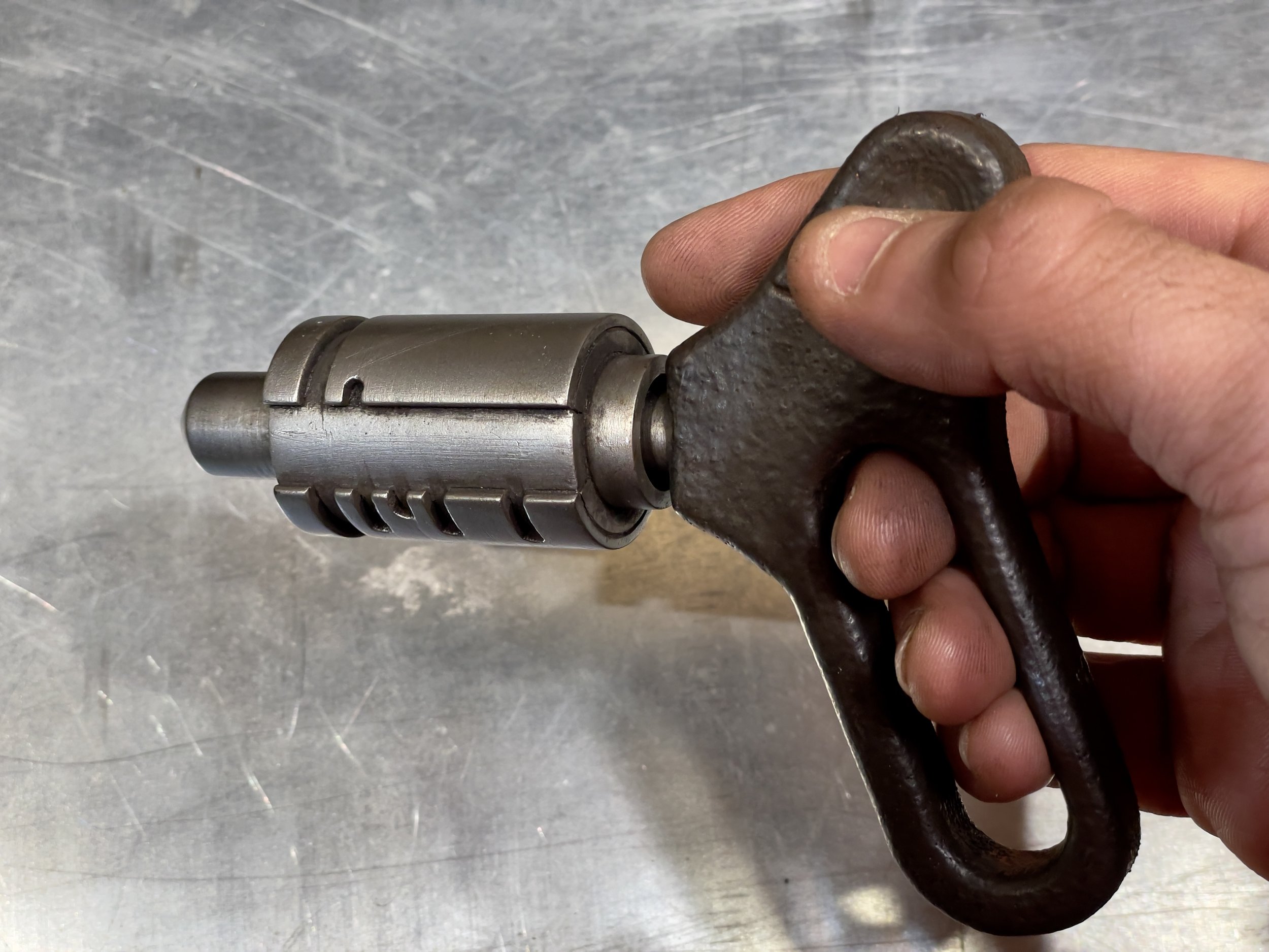
I did my best to carefully outline the handle using a Fit Point Spline and then used the Slot tool to make the appropriate cut for the fingers. Then I just needed to figure out the thickness of the handle. In the screenshot, Spike had a good grip on the key and it easily sat between his knuckles, so I determined the handle was at least 10-12mm thick (based on my own fingers). Considering the post that goes into the handle was roughly 11m, I settled on the handle being 12mm thick.
I filleted the edges of the handle for the rounded-over look seen on the keys in the show and then added the small key notches to the outer cylinder. Fusion 360’s Emboss tool made it simple to add the key notches. This tool is capable of embossing or debossing a sketch on a curved surface. The model started to match the screengrab.

First Revision Fits Well Within the Asteroid Blues Reference
Finishing Touches
The key was looking alright at this stage. It just needed some additional details, like the line across the handle (as seen on Faye’s key). I added the line on both sides of the handle along with a slight dip where Spike’s thumb rested in the reference image. The keys looked like they might have some sort of indentation to help the user turn the key to the right or from being worn down from heavy use.
I made some adjustments to refine the shape of the key and tried rendering a final version. It looked pretty close to Spike’s key if a little too clean.

The Final Render Before Testing Printed Parts
Test Flight
I exported the parts as STL binary files and loaded them into my slicer. I painted on supports in a few areas with large overhangs (the outer key jacket and the slot for the handle). The slicer estimated a little over 4 hours with a standard profile for my printer.

All the Parts Ready for Printing in ASA on an FDM Printer
Normally, I would print individual pieces to test them, but this is a small item without any complicated bits.
The first print showed me the handle’s fingers slot was maybe a little smaller than it needed to be, but it was hard to tell. When I held it like Spike in the reference image, I couldn’t fit three fingers in the slot. He had two fingers in the slot, but it was clear his pinky could fit alongside the other two. My fingers are thicker than Spike’s, so I could have gone either way. In the end, I decided to add 12mm to the length of the slot (enough to fit my pinky).
I also made a few small tweaks:
1mm chamfer at the base of the skinnier cylinder on the end of the key
Deeper thumb depression on the key handle
Deeper/thicker lines cut into the key handle
The chamfer looked nice and reinforced the model. The other changes accommodated my plan to lightly coat the handle in something like SmoothOn Urecoat or PlastiDip for a rubber texture. I didn’t want these details to be washed out or filled by the rubber. Also, on my FDM test print, the detail lines on the main cylinder were lost when printed against the print bed. The channels were only .4mm wide and .2mm deep-i.e., just one nozzle’s width and one or two layers deep.
Time for Ignition: Test Assembly
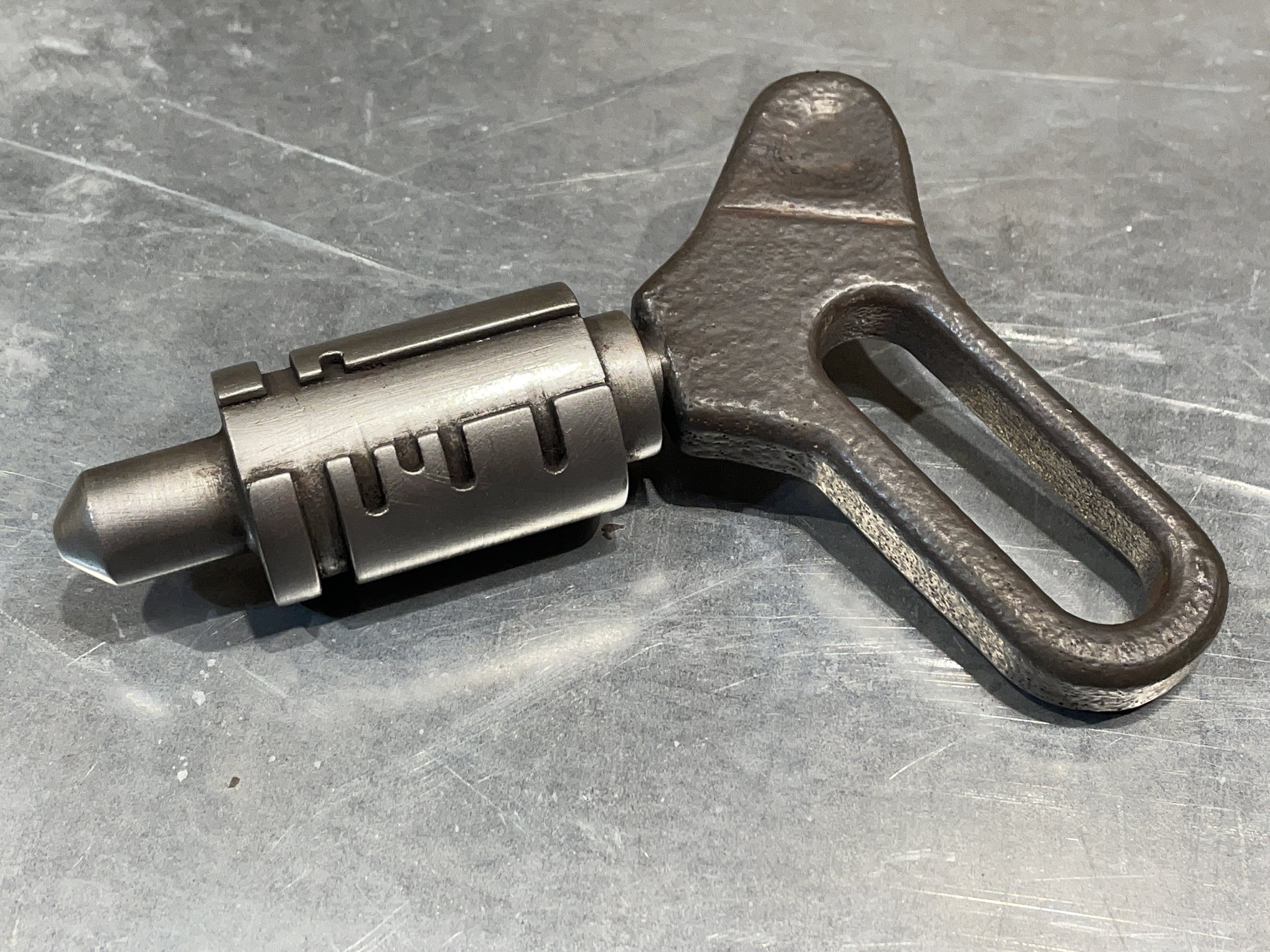
I printed each piece in Anthracite Grey Prusament Tough Resin on my Prusa SL1S printer. The grey color of this resin works well with parts to be painted with metallic lacquers. If the paint were to chip down to the plastic, the grey would look like it belonged alongside black primer and a weathered metallic topcoat.

Pieces Sanded and Ready for Assembly
I cleaned up the support material and test-fit everything with the brass bar at the core. If anything didn’t fit due to a print defect or shrinkage I needed to know that immediately before investing time into the part.
The parts fit really well, but I discovered gluing the outer jacket wouldn't be as simple as I had expected. First, I made the mistake of using BSI Insta Cure CA glue and applying glue to the main body and jacket. The glue on the main body set as I slid the larger jacket over it. It was impossible to reposition. I tried a second time the same glue worked fine but I wasn’t happy with it. The whole business was too easy to misalign or screw up.
I returned to Fusion 360 and added a very small 0.4mm chamfer to the edges of the jacket before combining the outer layers with the main body. The chamfers were just enough to make a fake seam, an area that would capture some paint during later weathering washes.
As an alternative, I also created a version that involved some fan fiction. In the world of Cowboy Bebop, all keys like this probably share a common core (the handle and inner cylinder). It’s the outer jacket with the notches that would be keyed to a particular zipcraft. To answer how a manufacturer would assemble a key and make the model a little more visually interesting, I added screw holes to the jacket opposite the notch. The holes fit M3 grub screws that can hold the outer jacket in place if printed separately.

Key with New Grub Screws Fixing the Outer Jacket in Place
Final Assembly
I fixed the top piece and brass rod in place with some 5-minute epoxy and taped off the rod to keep it clean for later. Then everything got a coat of Alclad II black microfiller primer. After I polished the primed surface with some micromesh, the key got a coat of Alclad II duralumin lacquer. I wanted a lighter-colored metallic finish that wasn’t as bright and shiny as their polished aluminum.

Assembled and Painted Key Pre-weathered with Scratches from a Scotch Brite Pad
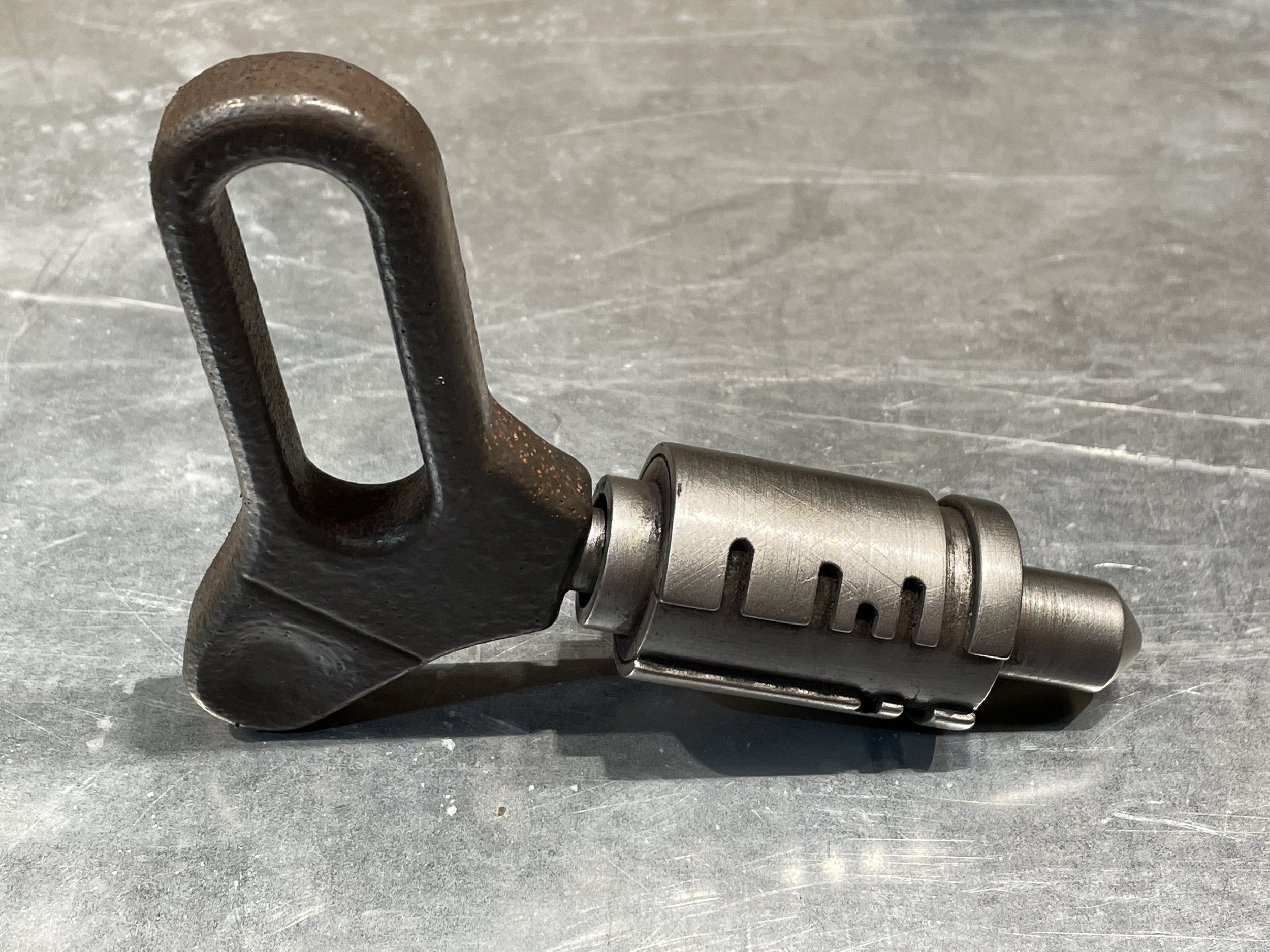
For the handle, I had a small amount of SmoothOn UreCoat, a brushable urethane rubber. UreCoat is a translucent amber color. The key handles in then show all appear as some sort of khaki or brownish-grey color, so I mixed in some brown dye with a little yellow and white. I stuck the handle on a wooden dowel and brushed on the mixture.
It was a disaster. I had so little UreCoat on hand that I couldn't mix multiple batches. That was a problem because the pot life of UreCoat is about eight minutes. Brushing the rubber onto a smooth surface proved to be difficult and required working slowly. The rubber thickened faster than I could work. I went to school with that experiment.
With the UreCoat spent, I tried a different idea: truck bed liner and PlastiDip. I love truck bed liner for adding a texture to surfaces and it’s really tough if the prop might get beat up. I sprayed a few light coats onto another handle to get a stippled texture. Then I sprayed on three light coats of black PlastiDip. This gave me a nice rubberized handle grip. The color was wrong, but the end result felt much better than a painted surface. In the future, I intend to try applying truck bed liner and then one or more coats of tinted UreCoat to achieve this effect in other colors.

PlastiDip’d Key Handle with Truck Bed Liner Texture
I let everything cure overnight before I permanently attached the handle to the brass rod with more epoxy. Next, I applied a topcoat of Alclad II Aqua Gloss to protect the paint from weathering paint washes. The weathering consisted of a few washes with water-mixable oil paints in brown and black colors. I added a little extra grime with one of my new favorite weathering pigments, Ammo by Mig’s metal slag weathering powder (https://www.migjimenez.com/en/ammo-paints/1140-metal-slag.html).
All that was left to do was wait the days/weeks for the oil paint to dry, but worth it for the greasy finish on my new Sci Fi zipcraft key.