Build Log: Ghostbusters Leg Hose Connector
There’s a part of the Ghostbusters uniform that many people hate. You include it for accuracy, but it’s floppy, catches on things, and is just the last thing you want to have to worry about when you’re already paranoid about the wand’s wire loom catching on something or turning and taking something or someone out with your proton pack. I’m talking about the leg hose.
To prepare for SiliCon 2021, I wanted to remake my leg hose attachments to meet several criteria:
Make the connector out of rubber, like the screen-used pieces
Make the leg hose secure but detachable if it catches on something
Make the leg attachment something I could easily remove if I needed to wash the uniform or just didn’t want to wear it
The leg hose connector is a rubber piece attached to the left leg of the uniform. The leg hose fits inside and is held in place by friction and, optionally, a 4mm wide zip tie. The other end of the leg hose is often attached to the pistol belt or just looped under it. The connector itself is sewn onto the leg of the uniform.
There are many designs for the connector and alternatives for how it attaches to the uniform. Likewise, many people have come up with ways for the leg hose to attach to the back of the uniform or belt. The design I came up with involved 3D printed pieces with threads and magnets embedded inside a rubber mold. Since then, I’ve come across similar ideas that used machined parts and other alternatives. For such a small piece of a costume, it’s really cool to see how people have approached this part in slightly different ways based on their personal skill sets and preferences.
Dimensions and Planning
To get started, I headed to the Replica Prop Forums (RPF) to see if there were any threads with good reference images. This being a Ghostbusters prop, there were many to choose from. I felt very lucky when I discovered RPF user Kormier’s drawing of the leg hose with all of the dimensions. I don’t know if their dimensions are 100% accurate, but Kormier showed their work, and - once modeled and printed - I thought the connector looked very much correct.
Speaking of different approaches to this, Kormier turned their connector out of wood on a lathe! How cool is that?
I took Kormier’s dimensions and modeled the connector in Fusion 360. Once I was happy with the model, I printed it in ASA and prepared it for a mold - i.e., did a lot of sanding.
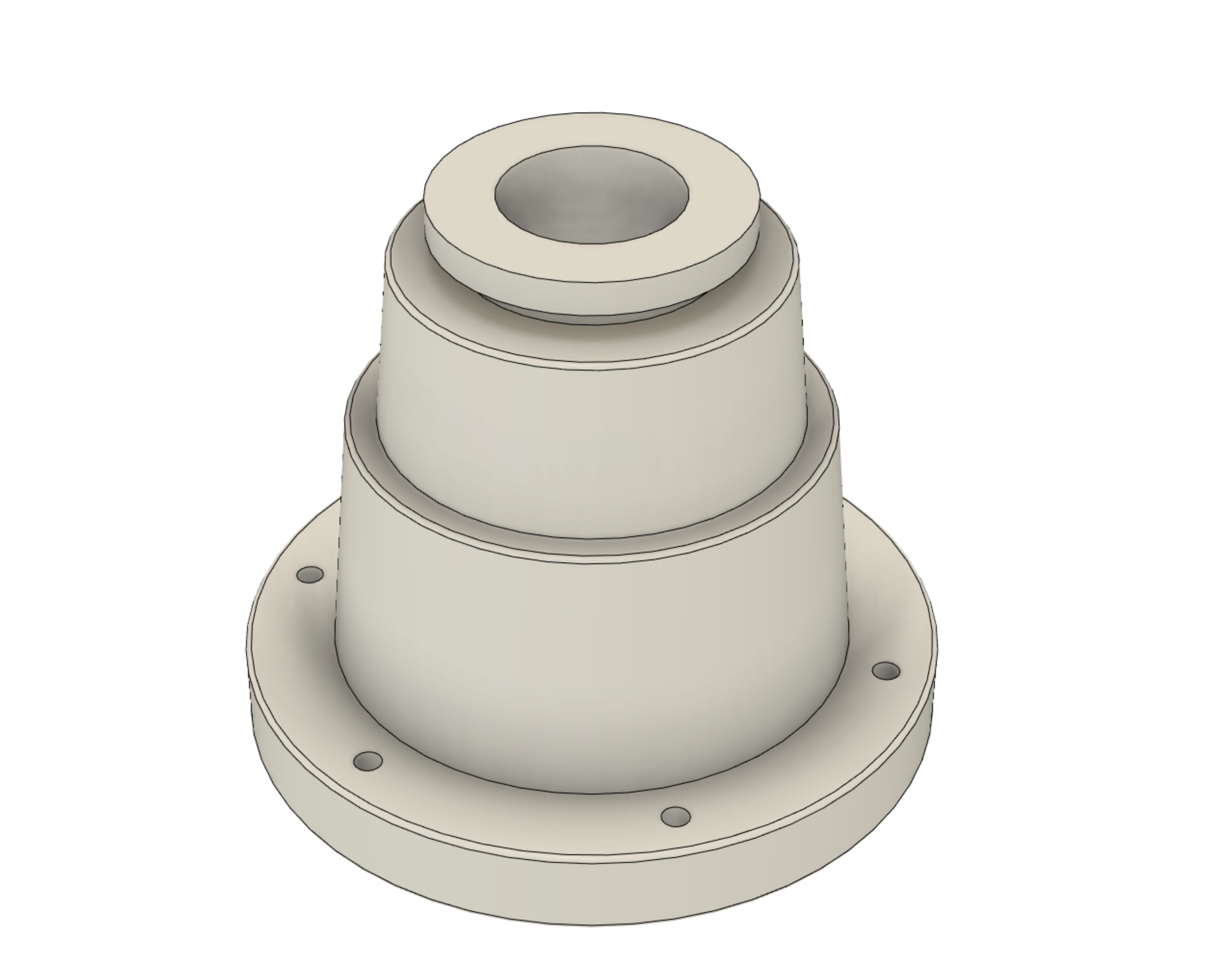
Model of the Leg Hose Connector in Fusion 360
The connector had a flat bottom with no details, so I could make a very simple one-part mold. The one consideration I had to make was what to do about the thread holes. I didn’t want to be part of the mold because the silicone would be far too thin and floppy, but I also didn’t want to have to figure out where to make the holes every time I made a copy. The solution was easy: stick clay in the holes from the bottom so there would be partial holes on the top showing where to drill or insert a needle and thread.
Next, I cast a copy out of Smooth-On Econ 60 rubber. Econ 60 is a translucent amber color so I had to dye it to get the proper color. This turned out to be tougher than it seemed, but that challenge came later. The casting looked pretty good, so I knew the mold would work and the design was solid. Now it was time to figure out how to attach it to my uniform.
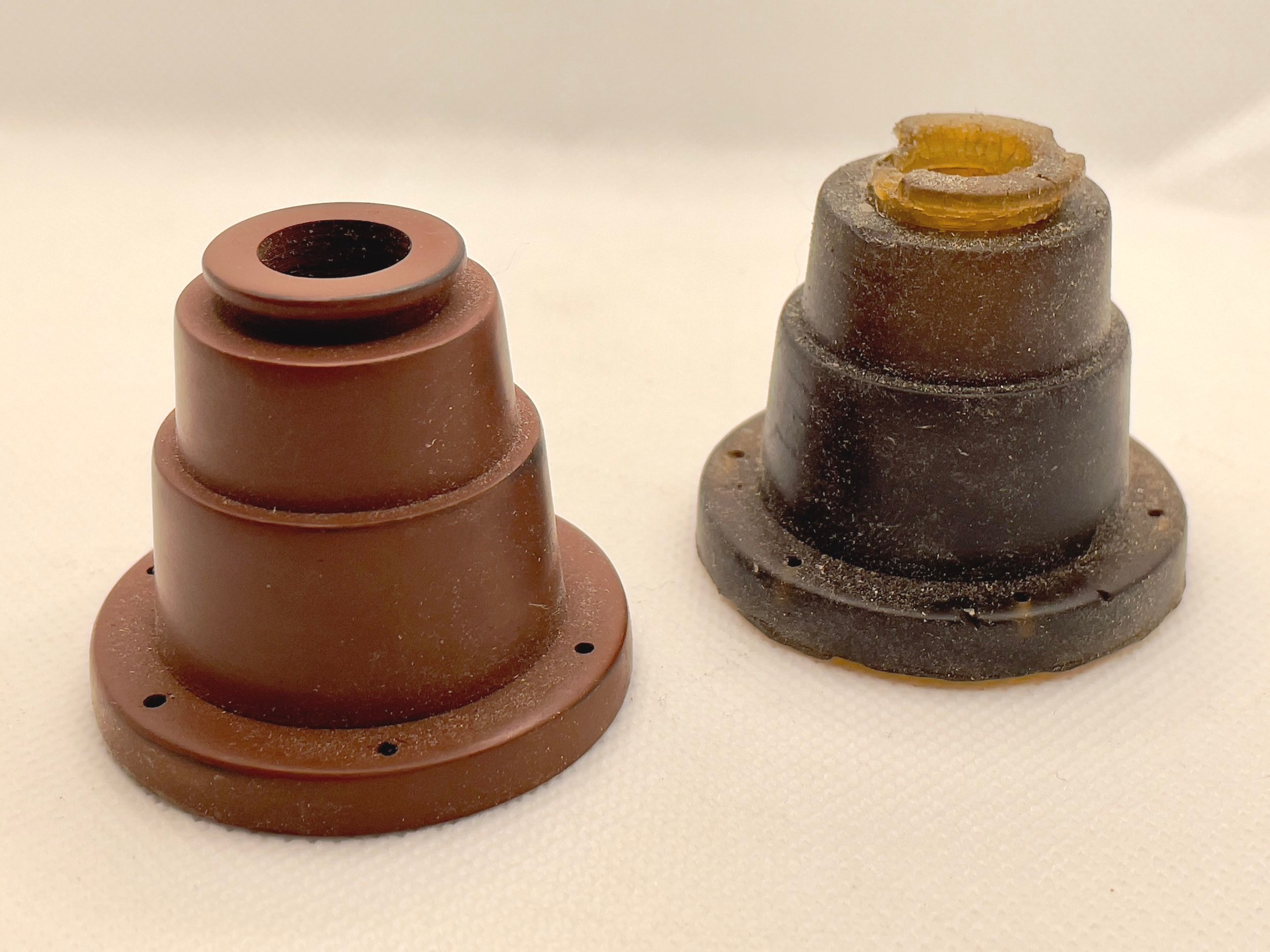
Here is what that first casting looked like without any dye and next to the original ASA print. Over a couple of days, it degraded and broke apart in some areas. I’m still not sure why this happened. I can only assume I got the mixture incorrect, but this is why you test processes when working with new materials.
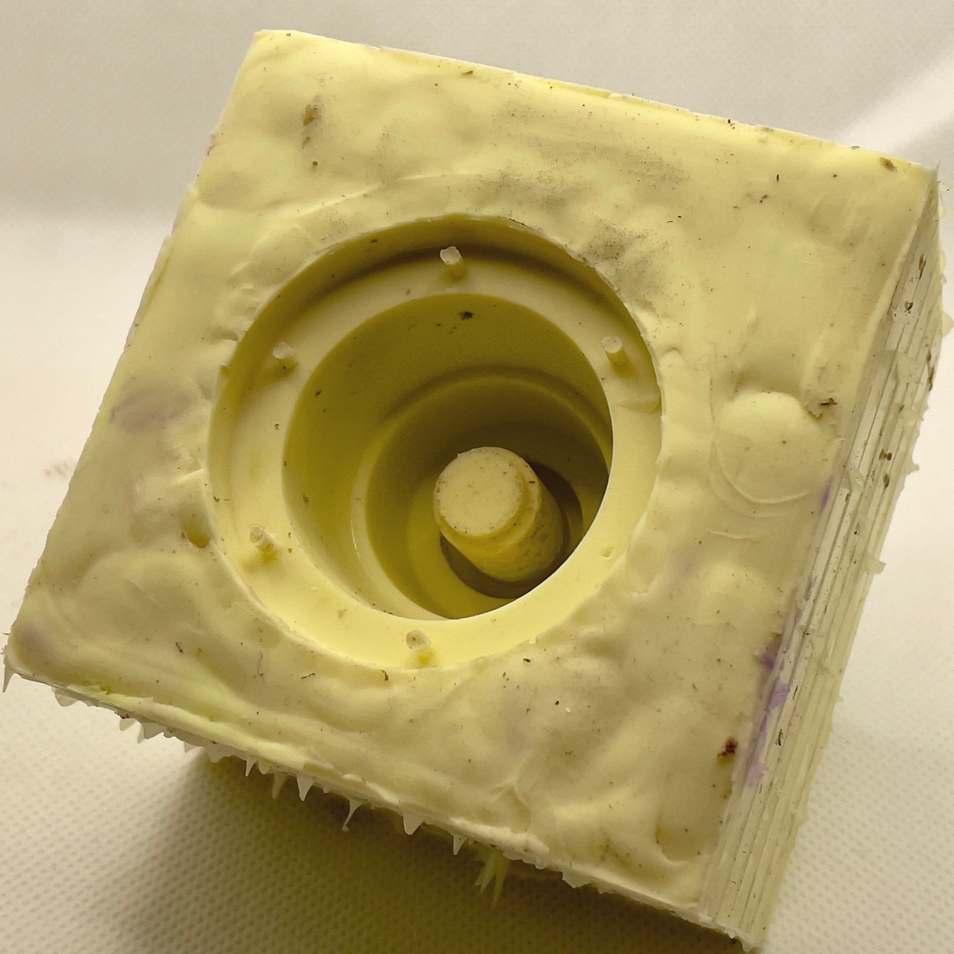
The mold may look a little rough because around the edges, but molds don’t need to be pretty. I made the mold box out of Lego bricks, so there’s a fun brick pattern on the sides and the top is bumpy because it faced some rough clay holding the original connector in place.
Test Fitting the Connector
I still wanted the connector to appear to be sewn on, so my first thought was some sort of plate on the bottom that would lock into a second plate on the uniform with a thread or twist lock. A threaded pair of plates were easy to design in Fusion 360. I printed them in PETG to test the idea and temporarily attached them to the ASA print with some thread. The idea was sound, but even very thin plates (<2mm) created a noticeable gap between the uniform and connector. The connector naturally sags at a ~45° angle (more or less), so the attachment point is very much on display when the uniform is worn.
Next, I toyed with the idea of moving the second plate inside the uniform. This would involve cutting a hole in the leg but would move the connector closer to the fabric. If the hose actually connected to something, there would be a hole in the uniform, so I committed and cut a hole in my flight suit.
Still, the plate on the bottom of the connector was visible and I wasn’t completely happy with the fit. I’d have to move the threads inside the connector, too. I know I could have reduced the diameter of the plate and nested it inside the rubber connector, but I worried that the weight of the connector and inevitable yanks or tugs on the hose would eventually begin to rip the plate away from the rubber.
I returned to Fusion 360 and modified the screw plate to be a sort of core that would go inside the connector. The core gained some cut-outs that would ensure the core remained embedded in the rubber and would never slide out.

Fusion 360 Cross-section Showing the Connector (Pink) with Threaded Core (Blue) Connected to Leg Plate (Orange)
I also modified the leg plate to have thread holes so it could be sewn onto the uniform and included some clearance for waxed thread (the sort used for leatherworking) sewn through the holes on the connector. That last detail would give the connector the appearance of being sewn on without the threads offering any actual support.
I quite liked this because the screen-used uniforms you can find in pictures and on display in various places all have sagging deformed leg hose connectors. Over time, the rubber breaks down and the connectors deform around the threads. By making the threads just a cosmetic detail I’d never have to worry about something yanking the connector and ripping a thread through the rubber.
Casting and Assembly
Now I had to get the right color. The surviving connectors are now decades old, so their color isn’t a great reference. From rewatching the films and discussions around the internet, I determined the connector should be close to the same color as my flight suit (i.e., a shade of khaki brown), but getting that color was tricky.
Note: The color of the adapter changes between Ghostbusters and Ghostbusters 2. The connectors are grey in the sequel and I was very much tempted to just make a grey connector after several attempts trying to get a brown I liked.
The secret to getting close to the proper khaki-ish color was a bit of yellow dye mixed in with brown and white. I didn’t have any yellow dye, so I ran to the store to fetch a yellow Sharpie marker. I cracked it open and squeezed some of its yellow dye into the mixture.
I was on a time crunch before SiliCon and couldn’t get proper dye in time. This felt like a crazy idea, but I figured Sharpie markers are alcohol-based, so it wouldn’t cause any issues with the Econ 60. It actually worked!
Before pouring the Econ 60 mixture, I glued a neodymium magnet into the small recess inside the PETG threaded core and then placed the core over the center post of the mold. The Econ 60 cured around the core and magnet, sealing the whole assembly inside the rubber.

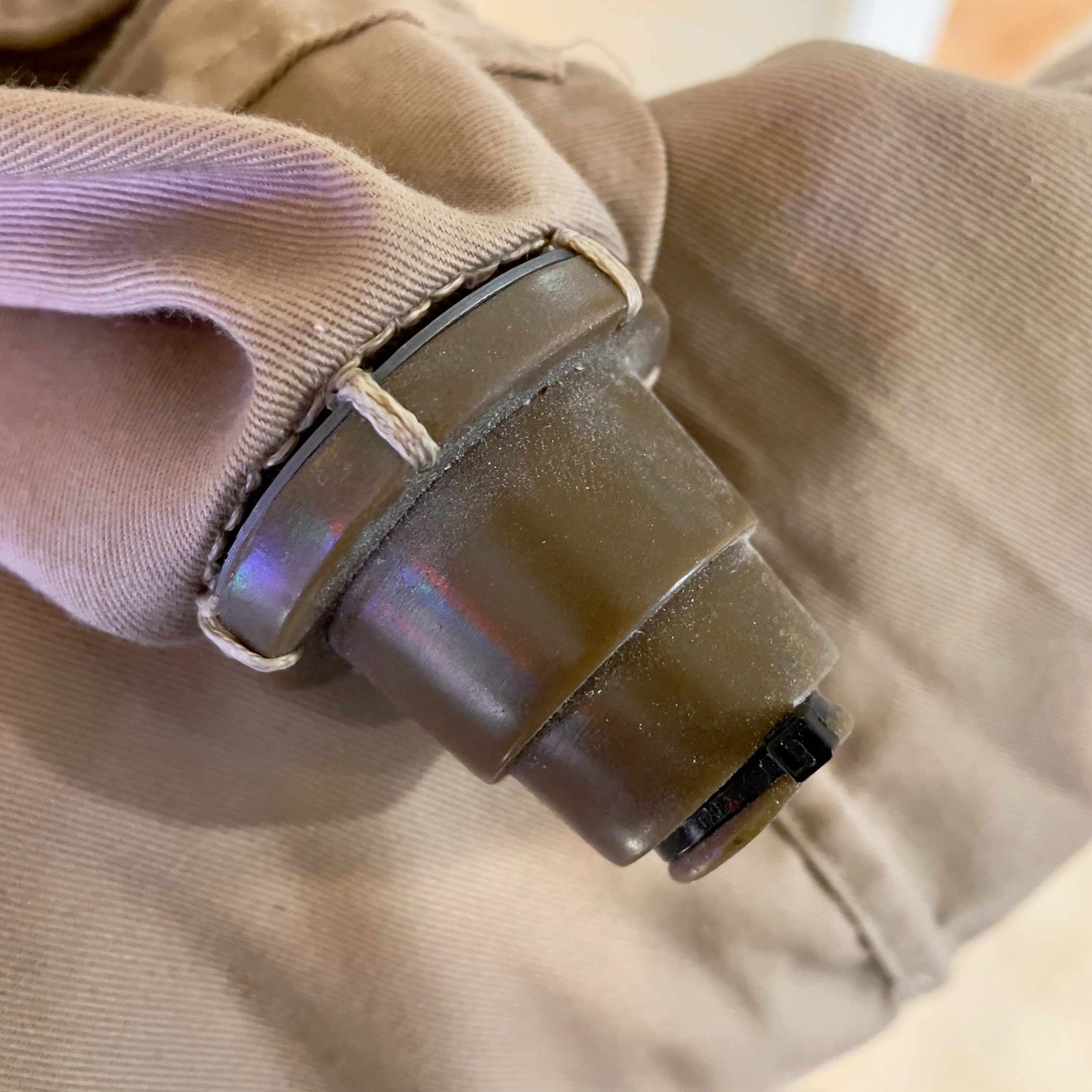
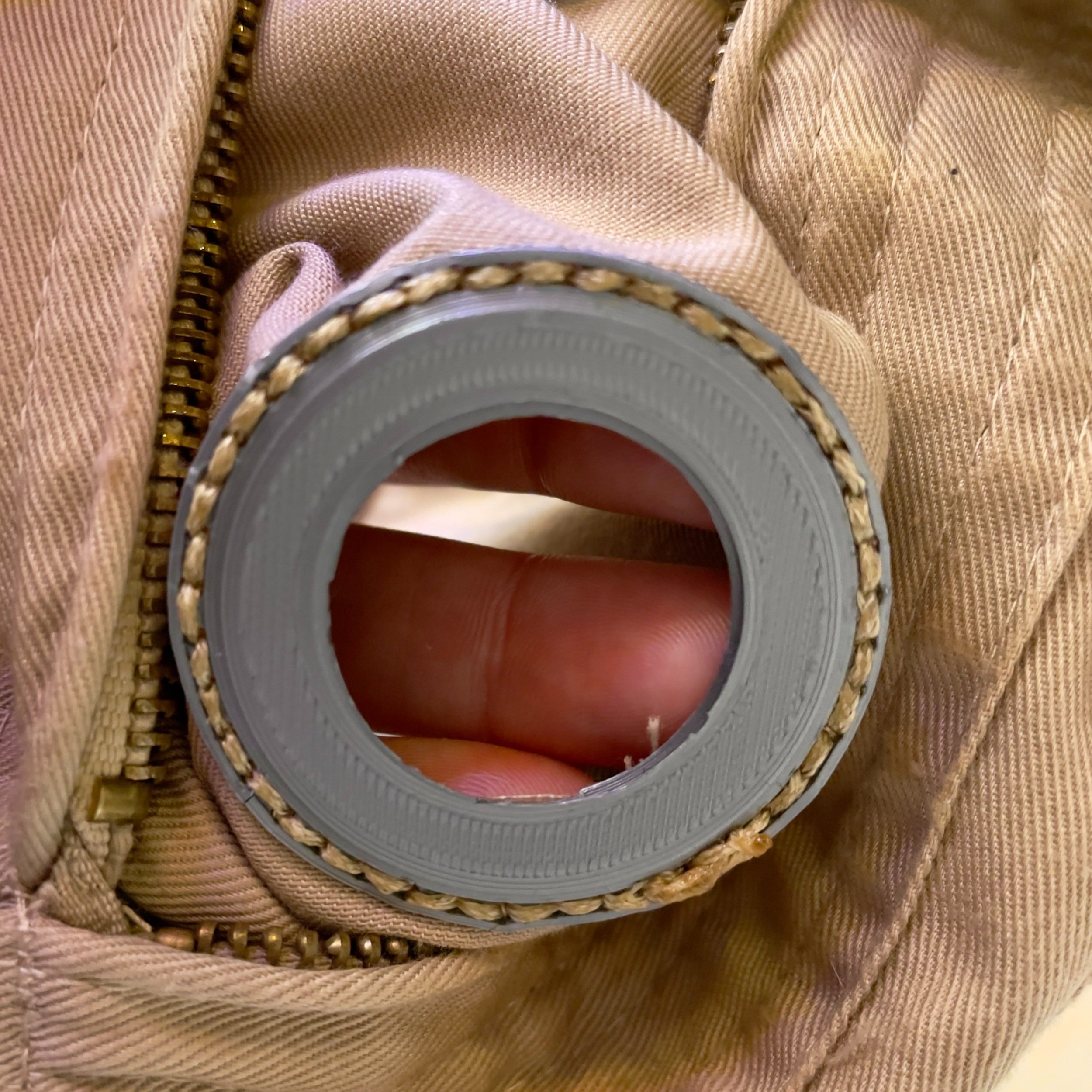
Final Leg Hose Connector with a Flush Connection to the Fabric
Securing the Leg Hose
To secure the ends of the leg hose, I created two barbed inserts that slid into either end of the hose. One insert held a second magnet and the other had a loop for a screw. The magnet end slid into the leg hose connector and stayed quite secure with a combination of magnetic force and friction. I discovered the holes in the pistol belt were perfectly sized for Chicago screws, so I used those to attach that end of the hose to my belt.

Hose Ends with Barbed Adapters for Chicago Screw and magnetic Connections
The typical ways the hose is secured to the belt usually involve cutting slits in that end and using a keyring or zip tie to attach it to the belt. That end looks slightly misshapen in the above shot because there are slits in the hose from using a keyring. I always worried the hose would get pulled and the keyring would tear through it. I’m much happier with this solution.
Real-World Testing
This setup worked really well at SiliCon 2021. The full configuration got tested when someone walked by me while I was getting a drink and snagged the hose. Everything worked perfectly! The hose connections failed as I designed them to fail and no one was tripped or taken for a ride. The one issue was the hose adapter with the Chicago screw. The screw held the adapter tight against the belt, so it was between two (mostly) rigid surfaces. When the hose pulled away from my body the adapter flexed against the screw and snapped along the layer lines.
When I got home, I re-printed it oriented sideways. Sideways isn’t an obvious orientation because round things don’t usually print well like that. In this situation, we don’t care about surface quality or maintaining a perfectly round barb because it’s a part meant to be hidden by a belt and proton pack. Making it so the layer lines would be perpendicular to the direction of force expected to be applied to the adapter was much more important. Now, if the hose is yanked and the adapter is pulled against the screw and belt it will be much less likely to break because the force is pulling against the layers.
Wrap Up
This was a fun project and I am very happy with how it turned out. I completed this about six months ago and in that time I have acquired a metal lathe. If I revisited this project in the future, I would likely take the 3D models and try turning the pieces on the lathe using aluminum and mild steel. While PETG should survive a washing machine (if I did wash the uniform, I’d wash it using cold water on a delicate cycle so PETG should survive with no issues), aluminum parts would hold up better over time and look really nice. Steel would work well for the hose inserts and remove the need for a second magnet and any worries about matching polarities.
Another potential upgrade would be replacing the threaded plates with some sort of twist-lock or an altered design that wouldn't leave an open hole in the leg when the connector was not attached. This is another reason a machined metal part would be a nice upgrade; it’d still look good as part of the uniform without the leg hose connector.
I still really like the general idea of the removable connector. If you don’t want to wear the leg hose, you can attach a substitute that acknowledges the connector should be there while also adding some sort of personal touch to your uniform. I got this idea from Bill Doran of Punished Props. I ran into Bill at KingCon 2021 while he was wearing his Ghostbusters uniform. Not a fan of the leg hose, Bill chose to sew a patch onto his leg as if he had removed the connector and patched the hole. I really enjoyed that idea and it inspired me to design a cover for when I wanted to go without the hose.
I whipped up a cover that mashed together valve designs from NASA and cosmonaut spacesuits. I couldn’t resist using some cosmonaut inspiration.
“What are you supposed to be, some kind of a cosmonaut?”

Leg Hose Connector Cover